I also experience this before on my build, taking off the board those 4 big caps eliminate this slight hum.
I tried to modify my own version of MKIII without those 4 big caps on board and makes this amp very very less hum but it's still there if i put my ears very close to the speaker but 1/2 meter disdance away i can't hear the hum anymore and its acceptable so far.
Regards,
I tried to modify my own version of MKIII without those 4 big caps on board and makes this amp very very less hum but it's still there if i put my ears very close to the speaker but 1/2 meter disdance away i can't hear the hum anymore and its acceptable so far.
Regards,
Attachments
still4given,
Cant you check each stage with your scope until you locate noise, whats DC offset...? i'm suspecting out of spec fake parts ..
Cant you check each stage with your scope until you locate noise, whats DC offset...? i'm suspecting out of spec fake parts ..
Hi Martin,
Did you get a chance to address some of this? I still have a very slight hum. It is very low and not noticeable when listening to music but it is still bugging me that it is there at all. None of my other amps do this. I tried attaching a resistor from star to case and it makes the hum worse. I have been working on other amps but I want to get back to this soon. I like the sound of this amp a lot so I really want to get to the bottom of this problem.
Thanks, Terry
Hi Terry-
I have the hum also. I'm still wondering about whether the shared ground on the board (that you identified) between the input and the rail bypass caps could be the source. Like you I've tried tinkering with the off board grounding scheme but nothing has helped. I will be modifying my amp to separate these grounds in the next several weeks. I will post results here.
Steve
If you are experiencing troubles, them it is time to tweak a little
If your grounding is fine, a good low resistance star ground...with the secondary center tap into the ground...then it is a good idea to see if you input is not shorting the ground...... if your RCA ground is grounded into the chassis, then you will be shorting your lifted input ground, as the input ground has a lifted ground that does not connect to the main chassis ground that is the star ground or the main ground.
I am offering you some obvious modifications, i am sorry to be so obvious, but maybe one or two guys will take this as usefull....
I have also reassembled one MKIII to inspect .... then i gonna do it today..it is curious people finding some troubles, also strange waveforms...i want to watch them myself.
regards,
Carlos
Attachments

Thanks a lot uncle charlie...
Will try to apply this modification today and revert back.
Regards,
Willy
Will try to apply this modification today and revert back.
Regards,
Willy
I will inspect the amplifier into the oscilloscope
Will see the strange signal that some guys reported.
regards,
Carlos
Will see the strange signal that some guys reported.
regards,
Carlos
uhmm ? interesting ... I still got my MKIII this will be interesting to updated in my note book.
regards
Juan
regards
Juan
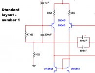
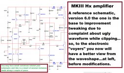
I have found a way to make the clipping much better
I found a mistake and i have supressed one component and also two rail diodes substituted by resistor if you want to make fine adjustment into the clipping simetry.
The hum effect can be reduce after you proceed with one modification i will show you.
Video being uploaded, more 30 minutes the working link gonna be posted...and it may be alike this one you see here:
MKIII amplifier behavior when clipping - Now much better - YouTube
I hope you like it guys....i have burned my finger upgrading the unit...at least that you like it.
regards,
Carlos
Last edited:
Carlos , we have you back , very happy with this, muito feliz Sir e Feliz natal para você .....
🙂
🙂
Hi Carlos,
I watched the video but you PCB is completely different from the one we have. Can you please post a schematic with the changes you suggest so I can see if it can be done on my PCB?
Thanks, Terry
I watched the video but you PCB is completely different from the one we have. Can you please post a schematic with the changes you suggest so I can see if it can be done on my PCB?
Thanks, Terry
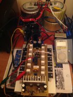
Here you have last images.
Uncle charlie is finishing DIY activities...almost 10 years cooperating with our comunitty providing you nice amplifiers to build.
Due to pirates copying all these years, all over the world, i have decided to stop, as i am working and they are earning money with my circuits.
From now on, only maintenance related old schematics posted along these last 10 years.
I would like to thank you by your preference and confidence and in my own forum i will develop new amplifiers....but circuit will not be provided, not DIY anymore..they will be made to show up and to sell by Zimmer.
I will not tweak any of my published amplifiers anymore.... if you want to do this, then do under your own risk.
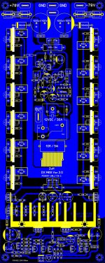
You gonna see differences in between versions and schematics due to tweaking and upgrading..several pcboards made, several batches of boards produced all over the world...and each of them may have minor modifications and sligthly different values or resistors...relax..all them work fine..... doubts go to layout creators and pcboards distributors.... Alex mm, Meanman, Byron, Juan Vargas, Miguel Nabuco (Mitchel) and Zimmer....these are the authorized ones....pirates you may have twice of that ammount and no one of them have ever sent me a box with biscuits as Christmas gift.
Layout honor goes to Alex mm..he is the one made it first..others improved but based into Alex work.
One guy from UK asked me the layout to produce some pcboards for his close friends..... it looks he has a lot of friends, as pcboards are still selling in the E Bay.... each day he makes more new friends.😕
Yes.... increasing stand by current you will have better performance..also increasing compensation capacitor from 82pf (schematic) to 220pf you gonna have more stable operation.. further modifications under our own risk..uncle charlie is now retired.
I will continue to give follow up to old amplifiers and to help non skilled builders.
To some few enemies made along these last 10 years... i would let you know that you are rid of uncle charlie.....hehehehe ... .but uncle charlie is rid from you too!
I wish God bless you all.
Be happy!
regards,
Carlos
Uncle charlie is finishing DIY activities...almost 10 years cooperating with our comunitty providing you nice amplifiers to build.
Due to pirates copying all these years, all over the world, i have decided to stop, as i am working and they are earning money with my circuits.
From now on, only maintenance related old schematics posted along these last 10 years.
I would like to thank you by your preference and confidence and in my own forum i will develop new amplifiers....but circuit will not be provided, not DIY anymore..they will be made to show up and to sell by Zimmer.
I will not tweak any of my published amplifiers anymore.... if you want to do this, then do under your own risk.
You gonna see differences in between versions and schematics due to tweaking and upgrading..several pcboards made, several batches of boards produced all over the world...and each of them may have minor modifications and sligthly different values or resistors...relax..all them work fine..... doubts go to layout creators and pcboards distributors.... Alex mm, Meanman, Byron, Juan Vargas, Miguel Nabuco (Mitchel) and Zimmer....these are the authorized ones....pirates you may have twice of that ammount and no one of them have ever sent me a box with biscuits as Christmas gift.
Layout honor goes to Alex mm..he is the one made it first..others improved but based into Alex work.
One guy from UK asked me the layout to produce some pcboards for his close friends..... it looks he has a lot of friends, as pcboards are still selling in the E Bay.... each day he makes more new friends.😕
Yes.... increasing stand by current you will have better performance..also increasing compensation capacitor from 82pf (schematic) to 220pf you gonna have more stable operation.. further modifications under our own risk..uncle charlie is now retired.
I will continue to give follow up to old amplifiers and to help non skilled builders.
To some few enemies made along these last 10 years... i would let you know that you are rid of uncle charlie.....hehehehe ... .but uncle charlie is rid from you too!
I wish God bless you all.
Be happy!
regards,
Carlos
Attachments

Last edited:
I'm not sure I understand your point. I always thought the whole idea of DIY was to copy and build. The boards I have are from Meanman.
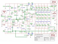
I have drawn where the grounds actually go which is different than your schematic. Please have a look and let me know what needs to be done to remove the rest of the hum I am getting. I don't care about the sign wave shape. I love the sound of this amp, I just want to get the ground scheme fixed so the it doesn't hum.
Thanks, Terry
Attachments
Last edited:
The board i am used came from Meanman
But from the first batch he made several years ago...your pcboard is modern.
Carlos
But from the first batch he made several years ago...your pcboard is modern.
Carlos
Yes I can see that. If you look at my schematic you will see that C11a&b, C15a&b and R8b all share the lifted ground with the input. It doesn't do that on the schematic you show. Could this be attributing to the hum some of us are hearing?
Thanks, Terry
Thanks, Terry
Hi Martin,
Did you get a chance to address some of this? I still have a very slight hum. It is very low and not noticeable when listening to music but it is still bugging me that it is there at all. None of my other amps do this. I tried attaching a resistor from star to case and it makes the hum worse. I have been working on other amps but I want to get back to this soon. I like the sound of this amp a lot so I really want to get to the bottom of this problem.
Thanks, Terry
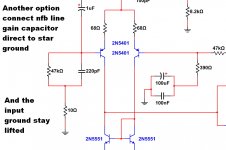
The screened cable helped a bit but not that much. I wonder how the lifted ground usage is influencing that noise. Carlos mention to send the 1st VAS collector to the chassis (star) ground instead of the lifted one. I'm not sure I want to change anything right now.
Carlos, I think you already mentioned that the bootstrap cap is what gives this amp its particular punch. I'm surprised that you suggest to remove it. Furthermore assymetrical clipping is not really a big issue.
I also wonder how you achieve not to stick to the negative rail without a baker clamp around the miller cap... the guys that tested the clipping behavior with a scope observed that sticking. (including me)
When I get some time I will try a few different things. Right now I don't have the star attached to the case. I tried doing that with a few different things including a 10R resistor, a diode, a resistor by-passed with tow reverse facing diodes and a just a solid wire. Each of them increased the hum. So far the best solution has been the 10R inline with the input grounds and the a 10R between the input ground and the case. The hum is very low now but not completely gone. I don't think I have a hum with any of my other amps and most of them just have the star connected directly to the case.
Blessings, Terry
Blessings, Terry
MK III hum
After looking at the board layout today I realized there might be a simple way to separate the input ground from the rail bypass grounds. The board provides multiple holes to accommodate different size input caps. If the Input terminal block is moved to the right so that the Sig Grd pin is inserted in the 3rd or 4th hole of the input cap string and the input cap trace is cut just right of this point then the hole just to the left of the Sig Grd pin can be connected to the star ground trace with a jumper or ground lift resistor. This should isolate the input ground and might help with the hum issue.
After looking at the board layout today I realized there might be a simple way to separate the input ground from the rail bypass grounds. The board provides multiple holes to accommodate different size input caps. If the Input terminal block is moved to the right so that the Sig Grd pin is inserted in the 3rd or 4th hole of the input cap string and the input cap trace is cut just right of this point then the hole just to the left of the Sig Grd pin can be connected to the star ground trace with a jumper or ground lift resistor. This should isolate the input ground and might help with the hum issue.
...
I have drawn where the grounds actually go which is different than your schematic. ...
Thanks, Terry
Terry,
I see some things that according to you are connected to the 'lifted' ground that I don't think would ordinarily be connected to the lifted ground.
C11a, C11b, C15a, C15b, R17 and R08b in my humble opinion would normally be returned to the star ground and not be coupled to the supposedly quiet lifted ground point. These items will inject some current through the 10Ω ground lift resistor, which creates a voltage across the resistor that is then handily applied to the amplifier input. Not what we would normally want to see. The only things I would personally place at the lifted ground are the input and feedback components.
Have you tried a jumper in place of the 10Ω resistor to see if things are better or worse? Not all amps need / benefit from ground lift and amy commercial amps have a switch so you can choose the quietest configuration.
- Status
- Not open for further replies.
- Home
- Amplifiers
- Solid State
- Dx Blame MKIII-Hx - Builder's thread