Terry,
how old are those main caps .....?
I'm not sure. At least 7 years old. I bought them before I got out of the hobby. They have been in a drawer for at least that long. I did reform them when I took them out. I just measured and I see about 24mVAC across the rails so maybe that is part of the problem. I will substitute in some known good caps and see if that helps.
Thanks, Terry
Last edited:
I'm not sure what you mean by input cables shields connected again. The shield of my input cables are the ground wire for the input. it only connects to the RCA and the - input lug on the PCB. They become connected when the source is connected because the source plugs have a common ground. This is very common.Common PSU is conected to two amp modules, and input cables shields are than conected again together.
I have the transformer as far from the input and output as I can.Ground loop, sensible to induction form magnetic fields. Transformer somewhere nearby. Result is induced current, causing voltage drop at cables shielding resistance, this is known issue.
You lost me here. What power module? I did install the 10R resistors. No change.Minimize loop area (twist input cables together, place power modules as close as possible) and minimize currents in input ground loop (use correctly 10R resistor separating power ground and input ground).
Thanks, Terry
Exactly, and hum in such topology (common PSU, unbalanced inputs) is also very common because ground loop induced currents (voltage drop at nonzero impedance of cables shields is added to input signal). Power module = one channel of amplifier..They become connected when the source is connected because the source plugs have a common ground. This is very common.
If You insert 10R in such loop (in each channel one independent resistor), shield resistance and 10R form voltage divider for such disturbing signal, and hum is much lower. To one end of 10R can be connected only input bias resistor ground end, input cable ground (shield) and ground point of NFB divider, nothing more! Other end of this resistor is connected to power ground (center point of PSU).
It can help a lot, but it is not the best possible solution (dual mono, independent PSU, or true balanced inputs..)
I
I can't understand your directions. Maybe something is being lost in the translation. I have built 14 amps. All with common PSU. This is the only one with this behavior.
Thanks, Terry
Exactly, and hum in such topology (common PSU, unbalanced inputs) is also very common because ground loop induced currents (voltage drop at nonzero impedance of cables shields is added to input signal). Power module = one channel of amplifier..
If You insert 10R in such loop (in each channel one independent resistor), shield resistance and 10R form voltage divider for such disturbing signal, and hum is much lower. To one end of 10R can be connected only input bias resistor ground end, input cable ground (shield) and ground point of NFB divider, nothing more! Other end of this resistor is connected to power ground (center point of PSU).
It can help a lot, but it is not the best possible solution (dual mono, independent PSU, or true balanced inputs..)
I can't understand your directions. Maybe something is being lost in the translation. I have built 14 amps. All with common PSU. This is the only one with this behavior.
Thanks, Terry
Main problem is, that 10R in DX Blame MKIII is simply missing
http://www.diyaudio.com/forums/atta...blame-mkiii-no-values-while-under-testing.pdf , input ground is direct connected to power ground , so ground currents are no way limited. With common PSU and unbalaced input it is the worst "solution".
http://www.diyaudio.com/forums/atta...blame-mkiii-no-values-while-under-testing.pdf , input ground is direct connected to power ground , so ground currents are no way limited. With common PSU and unbalaced input it is the worst "solution".
Main problem is, that 10R in DX Blame MKIII is simply missing
http://www.diyaudio.com/forums/atta...blame-mkiii-no-values-while-under-testing.pdf , input ground is direct connected to power ground , so ground currents are no way limited. With common PSU and unbalaced input it is the worst "solution".
Actually, if you look in this post, you will see R30, which is a 10R 1W resistor.
If posted pictures (schematic and PCB) are valid, than here are following faults:
To input signal ground should be connected only R01, C04, C06, C07 and one end of R31, 10R. To this point also should be connected input RCA ground , but input conector must be isolated from chasis. And nothing more!
To input signal ground can not be connected C15a, C15b,C11b C11a , it is AC short circuit from suplly voltage on signal ground (AC short circuit for 10R), via PSU main capacitors it is AC shorted to power GND! Also reconnect C01, R17, R08b to power ground.
In current state R31, 10R, have no function..
Last edited:
OK, now I see. R30 actually lifts the grounds of everything connected to that trace. Probably not the intention. That is probably why Carlos suggested to use a jumper there. I will try a 10R inline with the input ground. I wonder why no one else has reported a problem with this? According to Carlos, there have been many of these boards built. I wonder is any of this batch has been built yet other than mine. Other than the hum this amp really sounds quite nice.
Thanks, Terry
Thanks, Terry
OK Guys, thanks to the kind help from all of you I believe I got to the bottom of it. The first thing I did was pull R30 and reinstall the jumper per Carlos' suggestion. Then I installed a 10R 1W resistor between the ground wire and RCA connectors and connected the shield to the case per BV's suggestion. That completely eliminated the added hum when attaching both sides from the source. I still had some noticeable hum so I disconnected the power supply and connected up my DX PSU with a 40-0-40vac transformer. The amp is dead quiet now. Looks like I will have to fork out for some new filter caps. 🙁
At least I know what it all was now. I would recommend installing those resistors at the RCAs. It is easy to do and really made a difference.
Blessings, Terry
At least I know what it all was now. I would recommend installing those resistors at the RCAs. It is easy to do and really made a difference.
Blessings, Terry
Attachments

Good news dear Terry..... enjoy now your amplifier
It will give you a lot of pleasure i am sure.
regards,
Carlos
It will give you a lot of pleasure i am sure.
regards,
Carlos
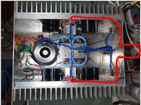
Hey I got rid of all the hum. I wanted to give the big transformer and caps another try. I still had the bad bum so I hooked up the DX supply once more and this time I had a hum. I noticed that the power cable was still attached so I unplugged it. The moment I did the hum went away. So now armed with this, I pulled the ground plate off my filter caps and enlarged the hole in the center so I could insulate it from touching the hold down bolt. I reattached everything using new mounting locations and now the amp is void of hum. I guess I will have to go with a bridge to attach the ground to earth. Whew, what a ride. Now I can finally concentrate with building some cases for the other 4 amps in need of one. 😀
Hopefully my journey will help someone else with their build.
Blessings, Terry
Hopefully my journey will help someone else with their build.
Blessings, Terry
Wrong, I never sugested that.. You only got lower level of hum, but for "blameless" function You need to change grounding (change PCB..), on upper side of 10R can be conected only R01, C04, C06, C07 and input cable shield. On the RCA conector the shield could be conected direct, and RCA (isolated from case) could by conected to case via 10R.Then I installed a 10R 1W resistor between the ground wire and RCA connectors and connected the shield to the case per BV's suggestion.
Sorry BV, didn't mean to misquote you. Regardless, adding the 10r resistors at the RCAs solved the problem and insulating the center tap from the case cured the rest. The amp is dead quiet now. I will not be modifying the PCB. This amp is finally playing nice so I am on to other things.
Thanks, Terry
Thanks, Terry
Hi Terry .Sorry BV, didn't mean to misquote you. Regardless, adding the 10r resistors at the RCAs solved the problem and insulating the center tap from the case cured the rest. The amp is dead quiet now. I will not be modifying the PCB. This amp is finally playing nice so I am on to other things.
Thanks, Terry
It's useful if you post a draft schematic .
Thimios.
I had to make one more change. Every thing was fine as long as something was plugged into the input but if nothing was plugged in, there was a bad hum. I had to short the input ground to the case to get rid of it. So my fix was to install another 10R resistor between one of the input grounds and the shield which is connected to the case. I'm not sure if a resistor is the best choice for this but it worked. If one of you thinks something else would work better here I am all ears. 😉
Blessings, Terry
Blessings, Terry
Please, ground your volume potentiometer case
the way shown in this video...approximately ate 06:20
How To Build A Tweed Deluxe Kit - YouTube
Ground wire goes to star ground, or center ground, or transformer secondary center tap or center screw or bolt and nut.
regards,
Carlos
the way shown in this video...approximately ate 06:20
How To Build A Tweed Deluxe Kit - YouTube
Ground wire goes to star ground, or center ground, or transformer secondary center tap or center screw or bolt and nut.
regards,
Carlos
Hi guys are interested in the construction of the blame right but I got lost in many post and my English is not that great. I wanted to know if it was done the comparison with other amplifiers such as krell ksa50 and what it came out as a result. of course I mean the sound quality in addition to raw power. or if you can tell me the link where you see the comparison with others. thank you
- Home
- Amplifiers
- Solid State
- DX Blame MkIII - 2013 builders thread.