Just because i love you gladiator Krachkiste, will let you figth three
times more, but this time against lions, without the Gladio.🙂🙂🙂🙂🙂🙂
This is because i love you the most.
Schwartznegger once said:
"Just because i love you, will kill you first"
In your case it is different, giving you the honor to face the lions... this way you will be famous the way you want and need.
Kidding of course........... i am not the Roman Emperor.
Carlus Imperatore
Attachments

Last edited:
No.D. Self showed the NFB point must be "exactly" in the middle of the emitter resistors for minimal THD.
Self and many others say the NFB tapping must monitor the output to the speaker and not monitor the half waves coming from either side of the speaker tapping point.
So, the way i have understood when reading, to follow exactly what Doctor Self wants
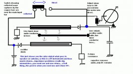
I have to install the speaker with the positive tap soldered into the board, because audio cable has Standing waves too, differences of phase between current and voltage, the same way we have with Radio Frequency transmission cables..... having standing waves, measurable using Standing wave meters (directional couplers) we can see this happening.
That was exactly the reason why i decide not to follow his advices about that, i feel that not a very good idea, despite i think he is a wonderfull designer and expert, a great man without doubts, but even great men have failures in their minds, some very extraordinary and delirant ideas sometimes
Because of that zobel filter must go to the speaker, inside the enclosure, soldered into the speaker terminal or into the enclosure back panel, in the speaker output posts.
Better to split them in two parts, one at the board, and other at the speaker terminal, or in three parts, one at the board, other at the speaker output posts and other inside the speaker enclosure..but need carefull calculation because will be a three pole filter, i am not using because i do not know how to calculate the stuff.
Standing waves in transmission lines, and speaker is an audio cable as coaxial cables are to Radio frequency too, are not something extraordinary or strange to Radio Amateurs, as we face this reality, we measure and we worry about each day...our transmitters burns when we do not control the standing wave ratio.
regards,
Carlos
Attachments
Last edited:
The real world is quite easy - take the NFB trace start point from the pin of output speaker terminal on the amplifier PCB (valid in case you have no output coil).
Last edited:
That's the way we use dear Pavel...but this does not mean it is the best possible way
You see that John Curl and others have supressed the output coil (I have included back again because users uses long cables)...so...time goes passing and people go realising that some uses are not the best practice.
regards,
Carlos
You see that John Curl and others have supressed the output coil (I have included back again because users uses long cables)...so...time goes passing and people go realising that some uses are not the best practice.
regards,
Carlos
Yes, for a while it is the best solution till reseach discover another, even better
way to do that.
Next board, for sure, will be made even better.
People can cut traces and run wires for a while, if they believe this may be better for sound reproduction
regards,
Carlos
way to do that.
Next board, for sure, will be made even better.
People can cut traces and run wires for a while, if they believe this may be better for sound reproduction
regards,
Carlos
Marcisium Laboratories, associated with the Corporation
have developed a SMPS power supplyr:
YouTube - proteus smps marcisio souza incompleta
regards,
Carlos
have developed a SMPS power supplyr:
YouTube - proteus smps marcisio souza incompleta
regards,
Carlos
the problem is that I cant adjust the bias .
it jump to 28 volts on both 100 Ohm resistors ,
does this mean the transistors in Oscillation mode ?
I checked every part trying to find what could cause that and nothing .
everything are good .... except that I cant adjust the bias.
Only one channel working with bias adjusted fine .
was working good and now 😕😕😕😕
Check the boards carefully, in special de one is oscilating, check
parts values.
What boards are you using, final board's version, from Dx Blame ES?
If you adjust and suddenly jumps to 28 volts, no doubts that this is oscilations.
Are cables fine?, is the enclosure grounded? are you using metalic enclosure or wooden enclosure?... is a wooden enclosure over a metalic one?.... is your amplifier exactly over a transformer, even having a metalic shield in between?
Search for differences... something is different in this second channel...maybe cables, position, transformers bellow, parts, bad solder.
Important, theres a cable that interconnects transformer's center tape... from this same junction you have a wire that runs to each one of the heatsinks.... this is grounding to the enclosure. when you have a metal chassis, usually the metal chassis interconnects all that stuff electrically when you connect both transformers center tap (when using two) to the chassis...good electrical connection must be done there.
Send me a picture of your construction, this will save my time to go searching of that rigth now.
use: carlos.eugenio1951@yahoo.com or nanabrother@hotmail.com
Good luck,
regards,
Carlos
Last edited:
I have found your construction dear Funky2x.... really man.... you were lucky
It has worked for so long time.
Have you soldered wires to the heatsinks, connecting to the transformer center tap?
Wooden case is dangerous, does not provide good grounding.... is your installing or moved your amplifier box from place?....are there anything bellow your enclosure, or bellow the amplifier..because wood is almost nothing for magnetic fields, does not constitute a ground plane for shielding?
I was very happy and surprised too, because i wooden enclosure have worked fine...in my home, my personnal constructions, usually does not work fine with wooden cases.... also cables are too much long, there are several suspecting spots there.
Someone said was scared and i have confirmed that....i felt myself lucky about your construction.... now i feel i was too much optimistic.
But i am very curious the way you have discovered that something is not fine... have you measured and adjusted once more?...interesting that people goes adjusting several times?
heheheheh...nice that.... this way you have discovered something wrong.
regards,
Carlos
Attachments

Last edited:

Nice wooden case, not only plays music but serves to burn in fire to make a barbecue
talking about Barbecue, i will go out for Carnival party downtown, we gonna have barbecue, but made using carbon, charcoal.😀
Downtown, the Old Recife, the town founded by the Dutch people a long time ago, will be near the first Sinanoga founded in the New world.... some of these Jews banished from here, when the Dutch depart from Brasil, then they travelled to a big Island in the United States, they have worked there building ships, and fishing, they founded a place, New Amsterdan i think...now a days called New York.
Yeah, jews from here, and i will be drinking very near their temple, Sinagoga is Jew religious temple... the ones that have stayed here, founded the street and keep the Sinagoga openned... they had to dig a lot to find the old sinagoga foundations, first stone and these things...i will be sitted, having my wine, exactly in the front of this building... a priviledge only my town has, to be so close historical monuments.
Shalom
bye,
Carlos
Attachments


Last edited:
Thank you dear carlos for the quicky respond.
Im using the final board's version ( 1.4 c ) .
the story began 3 days ago when I came back home and brother told me that something happened with the Amp .
first , I disconnected the power supply ( Method of finding where the problem ) .
it show a good condition 37 +/- volts .
then went on checking cables using DMM on diode test and nothing wrong with them.
then I checked the boards to see if there any burned part or cupper cut or bad joint and nothing ....
still more to check ..... Now time to check Transistors ...... they are all OK .. except BD139 ( the driver ) was in an open circuit .
relief came to my mind that everything will be ok after I found what caused the problem ... replaced with new one .
and after re connecting the power to adjust the bias and see if still there as did first time .
The first channel was OK , the second one came with a smoked resistors .... the two 100 ohms were very hot
I went another time checking parts on this board , all are Ok .
when I measure the volts on the two resistors like first time to adjust bias it jump as soon as I switch the amp ON to 28 volts ...
Wooooooow.
trying to get low voltage by trimming the trimpot left and right , Up and down . it stay there .
same time the resistors like a furnace . producing heat .
the leds which they indicate the power supply condition , used to stay on for about 4-6 seconds .. now they turn off in fraction of second ,
something consuming all the power ( in my point of view ) if am right and in a wrong way .
went again checking the parts and all are ok ...
Now am sitting here with Crossed fingers ... Alas .... Alas
dont worry Carlos , I still enjoy the sound playing but only with one channel .
at least I have something that satisfy my ears but ...
about the enclosure I use a wooden one and I use the traditional grounding . Star grounding .
one wire from the heat sink to the metal case of the transformer and another one to the power supply .. one wire from each channel and are all join together in one point .
My LCD monitor bellow the amp but it was there and playing without problem .
Yes, One thing I did before this occured .
I shorten the wires running from boards to the Transistors but after that , Was playing good and nothing happened .
Yes, I agree with you about the wires are a suspect .
Well, since I, who constructed this lovely amp . don't worry about me ...
all wires in color and easy to follow them .... but next time will take good care of avoid much wires
may be am A wires lover .... hahahahaha ... this how things works here with me .
enough for today and see you all tomorrow with good news .
I love this Amp .
Thank you Carlos .
thank you for the effort you do to this amp and the way you help people and ( me ).
Tinitus ... nice picture.
am not the only one who love wires .... hahahahahaha
No.
Self and many others say the NFB tapping must monitor the output to the speaker and not monitor the half waves coming from either side of the speaker tapping point.
Hi krachkiste,
Thanks for clearing this up, you are of course correct. I always try and place my output close to the middle of the output devices, or at least in the centre of the emitter resisitors, then take the NFB from the output (before inductor).
DX Amplifier PCB – Bottom Layer
Rereading D. Self it seems this is not neccessary as NFB will take care of any distortion. This has got me thinking about the take off point of the bootstrap.
regards
Yes dear Funky2X, no doubts this is oscilations, and killed the BD139, the upper rail
transistors, and this happened in my home too, when first amplifier was built, using Doctor Self CCS to feed VAS... then i have replaced with bootstrapp, this increased the sound quality but i found that i still had some oscilations in the top and bottom of square wave DC portion, the flat part.... the 100 picofarads capacitor, in the CCS, from base to coletor, and the 470 picofarads capacitor from the second VAS colector to ground stopped the oscilation...it was not so big in size, in voltage, the oscilation, but created that effect when we adjust the bias trimpot.
Well, it seems to me you should check these capacitors, they face high voltage, the VAS one faces all audio swing, i hope you are using a good one... check if you have these ones.... i remember i had leakage in one capacitor, down the eigthies.
Then remove what you have fixing the board to the wooden case and move the board, even beeing ugly try to make it high over the bottom, to change the wiring position, this may start oscilations, put that board, the one had troubles, alike and helicopter flying over the enclosure, and pull wires to be parallel to the board, wires going down...check once again if you have the 28 volts.... move board, twist and check it once again...sometimes, just moving the board from the rest position will move the wire that is creating the mess.
You know, wires, copper tracks, all that stuff represents resistance (very small) inductance and capacitances... sometimes , depending the way wires are positioned, they produce the ressonating circuit.
You can install 100 or 220pf in parallel with your VAS 470pf capacitor....in my testings only upper 1N we have bad effects to the square wave high frequency performance (inside audible audio band spectrum)...to compensate wires, maybe a bigger capacitor will make this unit (left?) more stable.
These tests with capacitor values were monitored using the Oscilloscope... i was curious to see how big it could be, because for sure theorical folks would be scandalized by the capacitor size... and they would accused me to slow down the entire amplifier..then i have checked as i know them very well.
I am glad you love the sound... i do love this amplifier too...unbeatable performance, each day a nice surprise to listen it once again with my old songs, the sound reproduction is much more clear than others, this makes audition and astonishing experience, i have never listened so good sound before....not even sound reproduction that could be evaluated as "almost so good as".... the advantage in sound quality is huge as you could see in your home.
Also old style method can be used... cardboard with one side having aluminium foil glued, attached to the cardboard... the aluminium foil, having the conductive side not glued and exposed to the air..then this goes under the board, a wire goes from the aluminium foil (fixed by bolt and nut) to the ground.... changing the distance from this shield to the board copper tracks, then you can stop some spurious oscilations...old style that worked several times in my home.... tape recorders, when using wooden cases, used this method because the bias oscilators (high frequency used to go together the audio to the tape recorder heads) used to be picked up by the circuit.
regards,
Carlos
Last edited:
If no one of these tries result fine, then use the killer method
take a 100pf capacitor and solder a wire to ground, the other extreme is free... use a rubber or a piece of paper to hold the capacitor between your fingers..goes touching transistors base, then colector and them emitter...all them, starting the first one.
During the use of "killer method" go monitoring that 28 volts you said... this means less than 300 miliamps each rail and the amplifier can survive..the heat is
less than 10 watts each rail (total of 20 watts) and fans may help....do the test for 1 minute and stop for cooling..then go again.
In special the VAS transistors may be the ones will stop the oscilations, seems there should be the problem... and with the previous 1K resistance the problem was worse.
Try to touch all parts, and both resistance and capacitor sides...and you will find the one will stop oscilation..solder the capacitor in place and be happy!
fixed!
regards,
Carlos
I told my brazilian friends and i have translated what happened to them
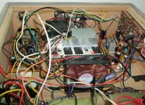
also i have sent them your picture Funky2x
They said their amplifiers are rock stable, that they have not faced these problemas, they have blamed your connectors and wiring..they said nothing is better than solder, wires organized in cable form, shortened and separating signal, supply, input and ouput.
One of them have built old style, but wiring was not very badly made...he had not troubles, also i had not trouble with three different styles, my case is also wooden case.
So, you have something to do, to build it better or to organize it better...please, remove all connectors, solder everything and do it good, with brigth solder results.
Good luck, i will look forward to your message saying have fixed.
regards,
Carlos
Attachments
if this amp sound so sweet in treble but with shy in bass then i think im gonna use it in my bi-amp.
Ill try this amp.
Ill try this amp.
Have you perceived the bass as shy?..... yep, i did perceived that
But the global, overall performance is great!
Rudi felt that too.
Volker have not perceived...he felt not shy..he felt bass enougth and fair.
Sergio Vaz felt the sound superior and flat
Comerlatte said the sound is ballanced, the bass is there, tigth and present.
Well.... several different opinions about...tastes, homes, acoustical environment, speaker ballance and aged ears or young ears.
regards,
Carlos
- Status
- Not open for further replies.
- Home
- Amplifiers
- Solid State
- Dx Blame ES .... based into the Blameless, i am trying a new amplifier