Everyone that enters our Corporation of cooperative fellows is a V.I.P.
Because these guys have good taste for good audio, they have good hearing and made the correct choice.
I leaned with Hugh Dean, the Master of Amplifiers, so, despite that i am (for sure, no doubts) worse than he is, i am becoming to be a little bit good too, that warmth in the sound reproduction,is there, and because the boostrapp , exaclty the way Master instructed me, even the current is not so different than the one he suggested me.
So, it is a matter to "join the good ones" to be a good one too.
regards,
Carlos
Last edited:
Sorry to jump all the way to the end without thoroughly reading all 64 pages between.
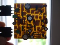
But I gotta say that construction method on Pg1 is awesome! I've seen the Manhattan
style before, where copper covered PCB islands are glued to a groundplane board. But
never occoured to me to simply gouge out channels on one side... What too did you
abuse to get such a clean groove?
But I gotta say that construction method on Pg1 is awesome! I've seen the Manhattan
style before, where copper covered PCB islands are glued to a groundplane board. But
never occoured to me to simply gouge out channels on one side... What too did you
abuse to get such a clean groove?
Germans did that way..was Rudi board design i think
I do not use this way, the main board offered in pdf files shows only the power amplifier.
But people is free to do this way, or a different way too.
I had troubles to understand you english...i have to learn more.
regards,
Carlos
I do not use this way, the main board offered in pdf files shows only the power amplifier.
But people is free to do this way, or a different way too.
I had troubles to understand you english...i have to learn more.
regards,
Carlos
Hi Carlos, I suppose that Kenpeter is asking for this construction method:
And how much fisical force is needed to peel off the channels from the plain copper
Great amp and great thread, by the way.
And how much fisical force is needed to peel off the channels from the plain copper
Great amp and great thread, by the way.
Attachments
Last edited:
Thank you hermano, i have used a steel metal blade used to fix transistors in place
The blade had a hole, in the corner of this hole i have used a screwdriver as a tool to create a blade for cutting.
The blade was sharpened using sandpaper.... i think i have made a youtube video about that.
We need to use some strength. after a couple of minutes you feel pain doing that, it is not the best way to do, for sure, it was the way i found.
I will search for the video to post the lin....
Here is the video:
http://www.youtube.com/watch?v=_HWIZo10YNo
regards,
Carlos
Last edited:
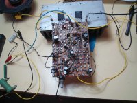
This other way is hard to be made, but can be used for emergencies
when we have no acid to etch boards.
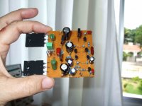
You trace your schematic in the component side, then you open holes to the component leads... the other side only copper and holes...then you join the common holes in big islands painted with a pen... islands that will join several leads together... them, the last is hard, you have to watch the upper side, then turn the board and paint the same thing under the board, the copper foil side... finishing that you use high speed drilling machine with a dentist ball point drill bit to remove copper in between the copper blocks that were painted in black.
This method uses some insulated wire jumpers, travelling bellow the board.
When i started i was very young, had not money to buy chemical products, then i have developed other ways to do.
Here is a video that shows some pictures while constructing a board:
YouTube - Dx Blame ES, board made high speed drilling machine
regards,
Carlos
when we have no acid to etch boards.
You trace your schematic in the component side, then you open holes to the component leads... the other side only copper and holes...then you join the common holes in big islands painted with a pen... islands that will join several leads together... them, the last is hard, you have to watch the upper side, then turn the board and paint the same thing under the board, the copper foil side... finishing that you use high speed drilling machine with a dentist ball point drill bit to remove copper in between the copper blocks that were painted in black.
This method uses some insulated wire jumpers, travelling bellow the board.
When i started i was very young, had not money to buy chemical products, then i have developed other ways to do.
Here is a video that shows some pictures while constructing a board:
YouTube - Dx Blame ES, board made high speed drilling machine
regards,
Carlos
Attachments
Last edited:
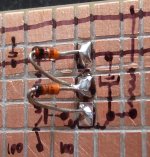
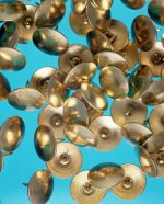
Other way, the first way i have used, was in 1960
Beach boys where playing "My 409" in the radio.
I used a piece of wood, and then i used a hammer and tacks, drawing pins, made of brass, things used to fix paper over a billboard.
So, i have used as connection points, as copper islands... telephone thin wire were use to interconnect .
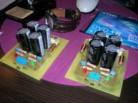
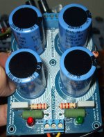
Here you have an image, a prototype board i gave to a local friend...this one etched and having circles as islands, to solder over the copper side (SMD was first made by uncle charlie)... this one is the Dx Blame ES, assembled this way, by my friend Egbert.
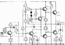
First graphic equalizer was also made by uncle charlie, i have used uA741 ancient operational amplifiers... uncle is very old, half century buiding amplifiers, the best one was found in 1970, the boostrapped, the one attached, since that moment, my love and passion by boostrapped amplifiers never ended... this thing was my first wife, the ethernal passion...real womans, also wives (3) i had several. and love finished three times, but for the bootstrapped the love and passion is still alive.
In 1964 i realised that pré amplifiers were not needed, and that i could have better sound without them...since that moment, no more pré amplifiers..only volume potentiometers.
I use all methods to produce boards, or a base to solder parts, when i cannot use the best way, then i use some secondary method..but amplifier's construction never stops.
Point to point, using thick wires, i have used to build Radio Frequency Linear amplifiers, power units..but only with electron Tubes.
regards,
Carlos
Beach boys where playing "My 409" in the radio.
I used a piece of wood, and then i used a hammer and tacks, drawing pins, made of brass, things used to fix paper over a billboard.
So, i have used as connection points, as copper islands... telephone thin wire were use to interconnect .
Here you have an image, a prototype board i gave to a local friend...this one etched and having circles as islands, to solder over the copper side (SMD was first made by uncle charlie)... this one is the Dx Blame ES, assembled this way, by my friend Egbert.
First graphic equalizer was also made by uncle charlie, i have used uA741 ancient operational amplifiers... uncle is very old, half century buiding amplifiers, the best one was found in 1970, the boostrapped, the one attached, since that moment, my love and passion by boostrapped amplifiers never ended... this thing was my first wife, the ethernal passion...real womans, also wives (3) i had several. and love finished three times, but for the bootstrapped the love and passion is still alive.
In 1964 i realised that pré amplifiers were not needed, and that i could have better sound without them...since that moment, no more pré amplifiers..only volume potentiometers.
I use all methods to produce boards, or a base to solder parts, when i cannot use the best way, then i use some secondary method..but amplifier's construction never stops.
Point to point, using thick wires, i have used to build Radio Frequency Linear amplifiers, power units..but only with electron Tubes.
regards,
Carlos
Attachments
Last edited:
Hello everyone!
Really a nice thread. I am feeling like coming around the world while reading it.
A comment on the standing current in the output devices.
According to D.Self a standing voltage over both emiter resistors at the output devices of 45mV was optimal for lowest distortion.
If you - rudi & co at german division - used 0R22 Resistors for R26/R27 this would be equivalent to a standing current of a nice and round 100mA.
So with 75mA the amp would still be biased even below optimal Class B.
Furthermore, if I interpreted the pcb-layouts that I've seen correctly, the NFB is taken off a point were the half wave currents from the output devices are not united back together to fullwave yet and thus beeing a potential source of unnecessary distortion.
Greatings from snowed in germany.
I see what you mean.
Well, about boards, it is up to Dx Corporation Canada (Taj)...if he want to modify all stuff....it is all rigth to me.
March 28, a new model upgraded and updated....will be released and Dx Germany will cross the Brandenburg port as celebration.
Please show us the best point....prepare a sketch please.
regards,
Carlos
Attachments

Last edited:


Furthermore, if I interpreted the pcb-layouts that I've seen correctly, the NFB is taken off a point were the half wave currents from the output devices are not united back together to fullwave yet and thus beeing a potential source of unnecessary distortion.
The NFB takes off on the PCB where it shows on the schematic -- between the 2 output emitter resistors. The only place further along would be after the output coil. That would require either a very long jumper or a complete redesign of the PCB.
I'm not sure Carlos is as obsessed about those .001 % potential degradations in THD as Doug Self is. I know I'm not.
..Todd
D. Self showed the NFB point must be "exactly" in the middle of the emitter resistors for minimal THD. Worth worrying about... don't know. 😕
I love the quality of your documentation Todd.
regards
No, absolutelly i am not obsessed... let it be the way it is
dear Todd.
It is sounding so beautifull, really, i am afraid to tweak once more...there are things so good that if you tweak they turn worse.
This amplifier is something this way, i have tried to increase impedance (the next model that i am afraid will never be delivered)... sounded terrible.
Well, will try more and more, once and once again, but results are not good till today.
I really have suspections this amplifier was inspired by other, not me,some spiritual entity, or a very lucky moment of my life, because resulted extraordinary, i have tried this kind of circuit several times, you can see the HRII is almost the same...but sound is not the same, this one is much better.
I am keeping my other models, without dismount, or trash them, because all them sounds good..but i am substituting all my amplifiers, the one i use together the computer, the one at my Home Theater , the Dx TriAmp and the ones at my daugther's home....because this one performer much better.... my amplifiers are being substituted by this one.
I do not think it is the best for bass, maybe i will keep a higher voltage bass unit, the Dx Standard, lovely for bass, not precise, not controled, but has thunder storm sonics, oil barrel sound, loooooog bass that i love.
For treble, midrange and sound stage...i doubt i will, ever, find one better than this Dx Blame ES.... was Hugh Dean (output), and Doctor Self (input) the ones that really have designed this amplifier.... i was just inspired by a good spirit, to join these things together.... another Frankstein, because now a days is almost impossible to be original...internet, fast wide world communications, everything now a days is an "arrange", in other words, copied.
There are many myths about these things fellows, i am a Radio Amateur and i found that even working with VHF, we can pick sinal in almost all length points of a copper track without face standing waves...if we can do that while working with 400 megahertz, for sure we can do that,without troubles, with 20 kilohertz.
I just try to offer some fashion parts, some Silver Mica, NP capacitors, because i know people believe this may be better, i have tried and i could not find advantage on theses things, i have compared, using relay and substituting parts, i have several "high end" capacitors sent by Greg and another aussie friend... i could not feel any difference.
They are included, because this way, people feel more interesting.... will match their belief the amplifier is high end because has some fashion, high end parts.... for me, really, unobtanium parts as i do not believe in fat lazy slow electrons or super electrons, nor in electrolitics that sounds...maybe i am ignorant, or stupid, but i have tried, i have compared, and i could not perceive difference, all them sounding absolutelly the same..topologie sounds, current choice sounds, VBE sounds, stand by bias point sounds..but parts does not sound... when you substitute a 2uf capacitor by another 2uf capacitor, them if you have difference, measure your capacitors..one of them has not 2uf..that's the reason....when you substitute electrolitics by a NP, you have advantage, not becasue one is better than other, but because the way the are constructed (non coilled) does not produce resistance to high frequencies..just a better choice, alike to select a better tool in this case, not because it is teflon or something alike... the internal construction, the way it is build matters...but things dopped with heaven fluids are just stories to fool us.
I love to satisfy people, if we could have, in a easy way, that feedback point captured alike Doctor Self told, then i would have more people building.... so, when i can, i do that way to have more people building, not because i believe in these things.
You see, this nice German guy (not sure about the flag, sorry) believe if you capture the output in the correct point will be better.... for me would be interesting to have that to offer him..because otherwise, he will not build, in his mind our board is defective.
I have worked selling Broadcasting equipments for Sony, i was the responsable for Brasil North and Northeast, and Sony show me clearly, give to them what they want...if they want zippa dee doodah then give to them, if they want some magic powder, detect what they want and offer to them...this way they will accept your product.
I believe what i feel, what i listen, in things i test, doing comparison.... only this way.
regards,
Carlos
Last edited:
Mammut PCBs
@Kenpeter
I assembled Carlos' Standard DXAmp 3 month ago.
This is how it looks like:
Although I am still (and every time anew) fascinated by its fresh, teenager-like sound, I don't like its mechanical design: too many wires running back and forth in the case.
And since in the meanwhile I upgraded the DXAmp by a small PCB implementing Speaker Protect (from DC), Speaker Delay (after Power On) and
Immediate Speaker-Off (to prevent the Power-Off "Plopp"), even more wires came running through the case.
Looking at my "commercially built" living-room AMP:
(or any other "brand AMPs" - hehehe -of AYRE, McIntosh, NAIM, ...) you see at least a "single PCB per channel" design.
Why shouldn't I do this as well?
So I merged together: Todd's beautiful layout Version 1.4c of the BlameES, Greg's power supply unit (the best one) and "my" Speaker protect circuit" and sent it as a PDF-file to my "etcher".
(The dimension of the board: 122 x 230mm is too big to try and etch it by myself.)
My "etcher" replied that he only accepts Gerber, Eagle, ... as input, but if I would give him an image with very sharp outlines he would try nevertheless.
So: I took my PDF file and re-painted it with "Microsoft PAINT" (no abuse of any tool, Kenpeter!).
And here is the result:
My design of the BlameES is an exact 1:1 copy of Todd's Version 1.4c design
Maybe my design will even allow a small improvement in sonics. (Hehehe - Carlos: open your eyes, please!)
All holes and components are in the same position as in Todd's layout.
But it is a rectangular design which is - from an electrical point of view - as stable as EAGLE's "spaghetti" design.
This is the way how I would like and assemble the BlameES:
The 2 "mammut" PCBs mounted on a big heatsink, 7KG of pure Aluminium (may be I will cut the ALU block in the midst to have 2 separate blocks).
This one will play in Brasil even if temperatures are more than 30 degrees Celsius.
Currently I am engaged in another "small project": giving the DXAmp (or the BlameES) the best attenuator ever (I will find out):
Best regards - Rudi_Ratlos - Vice-Chairman of DX Corp. Intl. German Division in Hamburg
@Kenpeter
I assembled Carlos' Standard DXAmp 3 month ago.
This is how it looks like:
An externally hosted image should be here but it was not working when we last tested it.
Although I am still (and every time anew) fascinated by its fresh, teenager-like sound, I don't like its mechanical design: too many wires running back and forth in the case.
And since in the meanwhile I upgraded the DXAmp by a small PCB implementing Speaker Protect (from DC), Speaker Delay (after Power On) and
Immediate Speaker-Off (to prevent the Power-Off "Plopp"), even more wires came running through the case.
Looking at my "commercially built" living-room AMP:
An externally hosted image should be here but it was not working when we last tested it.
(or any other "brand AMPs" - hehehe -of AYRE, McIntosh, NAIM, ...) you see at least a "single PCB per channel" design.
Why shouldn't I do this as well?
So I merged together: Todd's beautiful layout Version 1.4c of the BlameES, Greg's power supply unit (the best one) and "my" Speaker protect circuit" and sent it as a PDF-file to my "etcher".
(The dimension of the board: 122 x 230mm is too big to try and etch it by myself.)
My "etcher" replied that he only accepts Gerber, Eagle, ... as input, but if I would give him an image with very sharp outlines he would try nevertheless.
So: I took my PDF file and re-painted it with "Microsoft PAINT" (no abuse of any tool, Kenpeter!).
And here is the result:
An externally hosted image should be here but it was not working when we last tested it.
My design of the BlameES is an exact 1:1 copy of Todd's Version 1.4c design
Maybe my design will even allow a small improvement in sonics. (Hehehe - Carlos: open your eyes, please!)
All holes and components are in the same position as in Todd's layout.
But it is a rectangular design which is - from an electrical point of view - as stable as EAGLE's "spaghetti" design.
This is the way how I would like and assemble the BlameES:
An externally hosted image should be here but it was not working when we last tested it.
The 2 "mammut" PCBs mounted on a big heatsink, 7KG of pure Aluminium (may be I will cut the ALU block in the midst to have 2 separate blocks).
This one will play in Brasil even if temperatures are more than 30 degrees Celsius.
Currently I am engaged in another "small project": giving the DXAmp (or the BlameES) the best attenuator ever (I will find out):
An externally hosted image should be here but it was not working when we last tested it.
Best regards - Rudi_Ratlos - Vice-Chairman of DX Corp. Intl. German Division in Hamburg
Last edited:
Excellent dear Rudi, i see you still love the Dx Standard with passion
No problems to me...it is a Dx Corporation main product (we do not sell things..it is for free, a diy schematic)...we work for free..we help you for free..i would like to let this very clear.
Dx Corporation may be a real thing in the future.... and this happening i will not more use forum the way i am using not to have free advertising, i will go to the advertisers section, a paid section.
I would like to ask people that is going directly to my email, shy people that is afraid to ask things in this forum, not to do that, because questions and answers may be good for all forum folks, in special young ones, the beginners, the novices.... post questions here, to everybody know the answer.
Also i will be happy if people spend some time reading...this thread is not so big compared to other ones i have openned.... and i use to concentrate efforts here, also not to be repeating alike a scratched vinyl record or a drunk parrot, repeating all time long things already comented and posted.
I will take to myself the rigth to ignore some questions for parachutters, those ones land in the thread without read it since the very beginning.
We are having a very nice day in Brazil, sun is shinning and you may see images alike this one i took last year.
regards,
Carlos
Attachments

Last edited:
I could see you prefere the Dx Amplifier dear Rudi... you do not need to build the
Blame if you do not want..... we can produce high power (custom) to Dx Corporation Germany... a special Dx amplifier for a special Corporation support..you!... we can double this 8 ohms power very easy, or multiply it by 4 also easy... this way your mamute heatsinks will really work warm... this way it will be alike a freezer, a strong refrigerator..ahahahahaha!
Also the bunch or wires we can remove and substitute them by copper track..these were optional features because Doctor Self personnel, the ones have his book as a bibble, entered o suggest special grounding..them i let many options..the zobel ground was one of the discussed things, result was the one you see, you have to run wires for zobel grounding..we can change the stuff, to make a German super strong style...made to survive for more thousand years.
And much better, the modifications where assembled and tested, and passed!...were aproved!... so, it will not be an adventure..will be tripple guaranteed with four times quality certificate.
Not needed to promote the Blame...main target is customer satisfaction, and does not matter what model you will build..beeing a Dx model, it is all rigth.
HRII has crazy bass and very good treble, it may be an option, but some modifications must be done to turn it more and more stable and with less high end.
I see you will send boards for Belgium, you are not in a hurry to assemble, i feel you appreciated but you prefere the warm, strong and loosen bass.
This is not a problem...Kein problem...nichst problem..alles blau!
Build the one you want..and be happy my dear, this is the main produce we are selling, happy amplifiers made by an audio freak alike you all.
It is possible you have made a better board...who knows?... smaller distance between wires results in capacitances, bigger capacitance than Todd Johnson board..technically his board is much better..but sometimes, new capacitances and new inductances created (90 degrees angles) results in other ressonant frequencies, in lower frequencies, better to control...maybe you had made that miracle....
I do not need to open my eyes, i see you and i believe as a cooperator, not a competition.... despite you are great and good, and very helpfull, Greg Erskine is the board responsable by the Dx Standard and Todd Johnson is the main, official, Board designer from our Corporation, Alex mm is also a board designer from some products....you can be the board and layout designer for the German high power division custom amplifier, but will have to work hard as they did, not to find Todd board and apply retouches to it.
regards,
Carlos
Last edited:
- Status
- Not open for further replies.
- Home
- Amplifiers
- Solid State
- Dx Blame ES .... based into the Blameless, i am trying a new amplifier