thank you by your understanding.
Audio message was sent to you explaining my reasons with details.
regards,
Carlos
Audio message was sent to you explaining my reasons with details.
regards,
Carlos
I am very happy (and proud) to present you the first image of the EMEA Edition of the DX Blame PCB:
It is a dream in red and gold, worth to serve as the base for the best sounding amplifier in the world: Carlos' DX Blame.
I congratulate all of the members of the initial order: thank you for your confidence in METAL's and my efforts.
You all will soon receive a real masterpiece of audio - art.
Best regards - Rudi_Ratlos
An externally hosted image should be here but it was not working when we last tested it.
Great boards....looking great...nice colour.
Brazilian board will not be so good as your boards dear Rudi and Omar.
You have made a really great job.
Congratulations you two.
regards,
Carlos
Brazilian board will not be so good as your boards dear Rudi and Omar.
You have made a really great job.
Congratulations you two.
regards,
Carlos
Nice picture Rudi...the ligth reflections from the Gold that blurred the image
Just the angle....use 45 degrées and you gonna be rid of that.
Your camera is fine...very good one!
regards,
Carlos
Just the angle....use 45 degrées and you gonna be rid of that.
Your camera is fine...very good one!
regards,
Carlos
A thousand thanks to Rudi, Metal and Carlos for their work and for their DIYer altruism 🙂
Last edited:
This is my first real-world DIY PCB, manufactured and came to life. I am very happy and proud 🙂
PADs are nicely golden, silkscreen took much time, and here it is, just perfect!
Special Thanks to all members and friends who contributed making this PCB happen.
regards
Omar
PADs are nicely golden, silkscreen took much time, and here it is, just perfect!
Special Thanks to all members and friends who contributed making this PCB happen.
regards
Omar
Max!...i am preparing 26 videos explaining how the Blame works
In portuguese...Es fácil para usted? ....is easy to you to understand?
soon you will be able to see in youtube...just type "destroyersoueu"
regards,
Carlos
In portuguese...Es fácil para usted? ....is easy to you to understand?
soon you will be able to see in youtube...just type "destroyersoueu"
regards,
Carlos
Last edited:
Hi guys,
Yes, I can understand Portuguese, besides, your voice is sooo sexy 😀 that I will be delighted to listen to them...
Honestly, I had a lot of amp projects (postponed all of them) before you created this Blame and it was my plan to build them in strict order, but now I think I will just populate the boards and use my DX HR II PS to test the "Red Dragon Blame ES" 😎
The PS achieves around 34VDC. I hope it'll work...
Cheers and have fun,
M.
PS: now I will have to look at the BOM and see if I have what is needed... :-(
Last edited:
Thank you by the "so sexy voice"..... very kind from you dear Max
34 volts is fine...it can work from 12 to 64 volts (some modifications may be needed).
Sound better than HRII....you will be happy by your decision.
Enjoy the Super Sonics of an awsome amplifier!
regards,
Carlos
34 volts is fine...it can work from 12 to 64 volts (some modifications may be needed).
Sound better than HRII....you will be happy by your decision.
Enjoy the Super Sonics of an awsome amplifier!
regards,
Carlos
DX Blame How-To Video Series
Great videos Carlos! 🙂
I hope the guys from "the other forum" appreciate your efforts. 🙄
Cheers!
Great videos Carlos! 🙂
I hope the guys from "the other forum" appreciate your efforts. 🙄
Cheers!
Yes Duda...they are having fun with these videos
they will be copied and will go to a home page organized by Renato...then i will delete them to open room to produce other ones.
um abraço Duda (A big hug to you Edward)
Carlos
..............................
Line up
Please, read a little bit this same thread...or email me and i will return with an audio message to you:
carlos.eugenio1951@yahoo.com (1951 was a nice year)
Remotion of a 18pf capacitor from the NFB line...it was in parallel with 12K, the one is connected to the second differential transistor
Remotion of 470pf capacitor that was connected from the second VAS transistor to ground
Inclusion of a 10 ohms (now reduced to 2.2 ohms) in the second vas emitter
Increase in the value of the first VAS emitter resistance... in the early schematic (ES) it was 100 ohms....now increase to 220 ohms
The compensation capacitor in the VAS was increased from 82pf to 100pf
Rail resistances, was reduced from 220/150 ohms to 39 ohms to both rails
These are the main modifications.... visit Greg Erskine pages dedicated to the Dx amplifier and copy schematic, layout and enhanced image.
regards do Likeselle Lake
Carlos
Last edited:
Planning to start the building of the Blame ST with the boards of Rudi and Metal.Do I have to follow the Bom at Gregs website
(Inclusion of a 10 ohms (now reduced to 2.2 ohms) in the second vas emitter)Carlos wich one do you mean?(Rail resistances, was reduced from 220/150 ohms to 39 ohms to both rails) and this one?
What about the rail capacitors C20-22(470µF) can I use 1000µF there or is that to high?The reason is they fit better on the board.
Last edited:
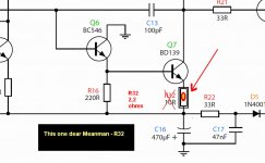
No problems about the condenser dear Meanman
You can use the capacitance you want there.... 470uf is enougth, and more than that will be waste of money...but will not create problems tilll you advance to values bigger than 40.000uf (or something big alike that)...there are books and big Gurús that say this is not good...i am not sure about that..i just avoid them to big too much big as i respect these big brains that have much more experience than i have....book writers usually have all that experience..or they will not expose themselves to criticisms registering ideas on the papper.
I am glad you will advance in your construction... i am sure you will never regret to take this decision.
The resistance you have asked i am showing in the schematic.... i found this one the best value...but the amplifier works very well using resistances from 22 to zero in that position.... tuned listening, i have perceived this value as optimum.... so...if you have problems to find small 2.2 ohms..you can use other value that for sure will not destroy your amplifier.
Greg pages of course have the most needed informations to builders.... if you have not visited..it is time to go there.
regards,
Carlos
Attachments
And those ones (Rail resistances, was reduced from 220/150 ohms to 39 ohms to both rails)?
About the 1000µF capacitors I've them on the shelf don't have to buy them.
About the 1000µF capacitors I've them on the shelf don't have to buy them.
- Status
- Not open for further replies.
- Home
- Amplifiers
- Solid State
- Dx Blame ES .... based into the Blameless, i am trying a new amplifier