Plan on post #83
latest sim and hr file on post#121
###########################
On my quest for a PA sub design that will let me reach 140dB SPL with 4 cabinets and do not use the 700+ Drivers from Beyma, 18sound and B&C that are staples
in high output PA cabinets
i looked for modest options and found a car driver that fits the criteria
since my hornresp skills are very modest, i can not simulate from scratch but punch in different drivers in to existing designs.
i think i found a winner combination.
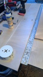
i will take 2 sheets of ply and 2 skar drivers
143 a piece per driver is 286usd for 3kw power per cabinet
the original design costed about 325 bux in 2013, i calculate that this will cost about 400 to 450
wood plus , handles, casters, paint.
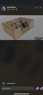
do you guys remember this LAB12 based design ?
https://www.diyaudio.com/community/threads/325-lab-12-based-pa-tapped-horn-35hz-extension.232219/

BP1 was very kind to help and do some mods to the original design that can only house a LAB12
he made S1-S2 baffle length longer so to accommodate 2 skar 12" drivers inline
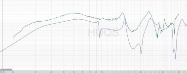
using 4 cabinets with 2 skar 12 DDX drivers @1.5kW per driver (3kw per cab) we get this


with HP and LP applied we get this

what you guys think?
tweaks ,mods, and improvements are welcome
Max.
latest sim and hr file on post#121
###########################
On my quest for a PA sub design that will let me reach 140dB SPL with 4 cabinets and do not use the 700+ Drivers from Beyma, 18sound and B&C that are staples
in high output PA cabinets
i looked for modest options and found a car driver that fits the criteria
since my hornresp skills are very modest, i can not simulate from scratch but punch in different drivers in to existing designs.
i think i found a winner combination.
i will take 2 sheets of ply and 2 skar drivers
143 a piece per driver is 286usd for 3kw power per cabinet
the original design costed about 325 bux in 2013, i calculate that this will cost about 400 to 450
wood plus , handles, casters, paint.
do you guys remember this LAB12 based design ?
https://www.diyaudio.com/community/threads/325-lab-12-based-pa-tapped-horn-35hz-extension.232219/
BP1 was very kind to help and do some mods to the original design that can only house a LAB12
he made S1-S2 baffle length longer so to accommodate 2 skar 12" drivers inline
using 4 cabinets with 2 skar 12 DDX drivers @1.5kW per driver (3kw per cab) we get this
with HP and LP applied we get this
what you guys think?
tweaks ,mods, and improvements are welcome
Max.
Last edited:
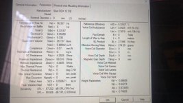
Those TS parameters are significantly off It seems
mmd is ~275
RE is ~3.9
LE @ 1k is at least 4.2
Qes ~0..33-0.35
Qms ~ 5.1-5.2
Vas is ~22.5 -23 liters when spanked at 20 hz for 18 hrs or so in free air. Otherwise it’s stiff as heck
Fs ~38-38.5hz
mmd is ~275
RE is ~3.9
LE @ 1k is at least 4.2
Qes ~0..33-0.35
Qms ~ 5.1-5.2
Vas is ~22.5 -23 liters when spanked at 20 hz for 18 hrs or so in free air. Otherwise it’s stiff as heck
Fs ~38-38.5hz
Attachments

Last edited:
so this ones are not good ?
looks like its the price to pay when you get car drivers who the manufacturer do not want to invest time/money to break the suspension
to standardize the Thiele small parameters

looks like its the price to pay when you get car drivers who the manufacturer do not want to invest time/money to break the suspension
to standardize the Thiele small parameters
We ALL hate FB, but this info and DDX driver experiences are well established there . Lots of TS data from many people so you guys can develop a great TP/TH. I’ll copy it 💚I still have one ddx 12, gave the others to my nephew(who could use a cool enclosure too) to play with
they murder it in ROAR fwi (so assuming your TH will be exciting)
they murder it in ROAR fwi (so assuming your TH will be exciting)
Last edited:

Heres another legit example for the ddx12 that might help 🙏🏻
Attachments
Last edited:
Modern car audio drivers with Qts < 0.40?
Hmm...
I'll believe that when actual measurements show that to be the case...
Hmm...
I'll believe that when actual measurements show that to be the case...
well assuming the T/S parameters are sorted out its accurate the difficulty is working out the fold fitting the two drivers in. One input on your simulation is that you should only need a 4th order high pass to control excursion, using an 8th order filter just adds extra group delay. I would also want to cross this box over at lower frequency than 100Hz, I expect there is some weirdness in the group delay associated with the spikes in the freqeuncy response towards the end of the pass band.
I have a little skepticism about the driver, 1000W seems a lot for a 2.5" coil considering that is a normal rating for a 4" coil. I tend to be of the opinion that you generally get what you pay for with pro audio drivers, having used things like car audio drivers in the past for PA. But nothing in the T/S parameters people are posting looks 'bad' and people are reporting good results in other cabs so it could just be better value due to the lower cost of production in south east asia compared to Italy.
I have a little skepticism about the driver, 1000W seems a lot for a 2.5" coil considering that is a normal rating for a 4" coil. I tend to be of the opinion that you generally get what you pay for with pro audio drivers, having used things like car audio drivers in the past for PA. But nothing in the T/S parameters people are posting looks 'bad' and people are reporting good results in other cabs so it could just be better value due to the lower cost of production in south east asia compared to Italy.
moving S3 to 300 and L12 to 47.8 get rid of the above 100 spike and makes the passband smother
i don't know if those tweaks can be translated in to the real cabinet

i don't know if those tweaks can be translated in to the real cabinet
I used the txt file that Max provided to model the enclosure.Those TS parameters are significantly off It seems
mmd is ~275
RE is ~3.9
LE @ 1k is at least 4.2
Qes ~0..33-0.35
Qms ~ 5.1-5.2
Vas is ~22.5 -23 liters when spanked at 20 hz for 18 hrs or so in free air. Otherwise it’s stiff as heck
Fs ~38-38.5hz
|HORN PARAMETER VALUES:
S1 = 171.45
S2 = 219.45
Con = 21.00
F12 = 0.00
S2 = 219.45
S3 = 445.70
Con = 89.68
F23 = 0.00
S3 = 445.70
S4 = 1107.60
Con = 193.30
F34 = 0.00
S4 = 1107.60
S5 = 1175.00
Con = 16.00
F45 = 0.00
|TRADITIONAL DRIVER PARAMETER VALUES:
Sd = 510.00
Bl = 31.80
Cms = 7.00E-05
Rms = 14.80
Mmd = 226.60
Le = 0.00
Re = 6.80
I LIKE that design! It reminds me of the 4 x 12" BP4 I built for my son's old Mazda Protege. He's using it now for home theater.Another ‘roar’/TP/TH that worked great with ddx12s
kind of this one, but this one have one straight segment per side and then a MAZE!!!

does it count as an Expansion horn or something ?
if you see every cavity have a bigger area as it go towards the mouth

does it count as an Expansion horn or something ?
if you see every cavity have a bigger area as it go towards the mouth
With booger parameters i got thisI used the txt file that Max provided to model the enclosure.
|HORN PARAMETER VALUES:
S1 = 171.45
S2 = 219.45
Con = 21.00
F12 = 0.00
S2 = 219.45
S3 = 445.70
Con = 89.68
F23 = 0.00
S3 = 445.70
S4 = 1107.60
Con = 193.30
F34 = 0.00
S4 = 1107.60
S5 = 1175.00
Con = 16.00
F45 = 0.00
|TRADITIONAL DRIVER PARAMETER VALUES:
Sd = 510.00
Bl = 31.80
Cms = 7.00E-05
Rms = 14.80
Mmd = 226.60
Le = 0.00
Re = 6.80
does it count as an Expansion horn or something ?
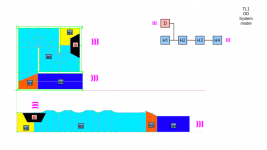
It's just a Paraflex design, it counts as segment.
Attachments
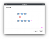
No, a transmission line in general has two sound output (pink waves in the system model) while paraflex has just one. The way the segments are connected are different too.
Try to compare the system model (square segments with names, H1, H2, etc) with the colored region regions in the box layout.
Each model will have different amount of segments and they will be connected in a different way.
Try to compare the system model (square segments with names, H1, H2, etc) with the colored region regions in the box layout.
Each model will have different amount of segments and they will be connected in a different way.
Attachments
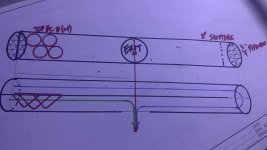
This one has the very same discontinuity in it that I experienced in paraflex and dreaded as it was missing freqs and then ringing further up/down scattered in that region (time domain and group delay junk in the sim or more technical discusion by Scott Hinson ) .kind of this one, but this one have one straight segment per side and then a MAZE!!!
View attachment 1140362
does it count as an Expansion horn or something ?
if you see every cavity have a bigger area as it go towards the mouth
View attachment 1140365
my buddy built that one with 4ddx and it was fire wood by the next week because it was unlistenable in that region..
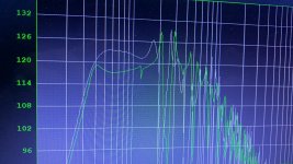
upon further investigating, in sim and practice, you cannot smash two resonators together in parallel that are huge/short AND long/skinny because they never work ‘ perfectly’ unless it’s 3:1 in length and similar in crossection.
play with tubes and you can create the white graph(no phase discontinuity) quite easily (ignore the green, it’s the 4th order offset driver at 1/3 from closed end this replaced in the experiment to sort these out with HR as our guide ). Impedance sweeps and scrutiny with test tones in the area seem to agree
we are using these indoors and in SUVs so a PA application might be more forgiving , but….(?)
you MUST respect the 3•Fb of the longside and aim at it or suffer the xo region and consequences of outta phase
Attachments
-
 4E5D4F31-BBB6-47FD-8BC7-8B96587CD529.jpeg607.8 KB · Views: 122
 -
 A7E512EC-2429-4D08-8A77-B27F25B4335C.jpeg45.4 KB · Views: 114
 -
 81B0F7C9-77A6-4E7D-929C-890084BE417C.png71.2 KB · Views: 121
 -
 D9DA64A7-99B2-4C87-8AD2-B5F4B80B1518.jpeg307.5 KB · Views: 114
 -
 04ADA02C-A75D-49D2-84ED-B4751DB565A9.jpeg470 KB · Views: 113
Last edited:
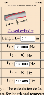
If you look at the younger paraflex models they really do a heck of a job fixing this area it seems. hats off to Matthew and crew for always chasing the details. If you want to get ahead if this:
http://hyperphysics.phy-astr.gsu.edu/hbase/Waves/opecol.html#c1
maintain the crossectional (or you can split it in 2 as seen in HR modeling ) and split the length from stsrt(s) to exit as 3:1…. Stuffing will polish the rest
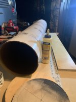
In HR, the ddx12 likes ~200 cm2/each and bumping that to 400cm2 in the second half of my ‘real world sonotube ‘pipe’ model’ shows why 2 drivers @ 400/800cm2 both fits the lengths of resonators but also the motor and pole vents of a pair mounted side by side inline.
http://hyperphysics.phy-astr.gsu.edu/hbase/Waves/opecol.html#c1
maintain the crossectional (or you can split it in 2 as seen in HR modeling ) and split the length from stsrt(s) to exit as 3:1…. Stuffing will polish the rest
In HR, the ddx12 likes ~200 cm2/each and bumping that to 400cm2 in the second half of my ‘real world sonotube ‘pipe’ model’ shows why 2 drivers @ 400/800cm2 both fits the lengths of resonators but also the motor and pole vents of a pair mounted side by side inline.
Attachments
Last edited:
- Home
- Loudspeakers
- Subwoofers
- Dual Skar12 paraflex C CRAM