Good ideaWe need TO-3 !!!
comment from Gary s
If you want to stay with the TO3 types, then I would look at the available On Semi MJ11015G/11016G darlingtons.

Those transistors can handle 25A. It's a good alternative solution but if you want TO3 On Semi MJ11015G/11016G darlingtons as Gary S has mentioned previously, is better. there are also MJH6284/87 TO247 as 2N6284/87 alternatives.I guess it was a little bigger with TIP35C+TIP36C on the out
Hi metanastis- any chance you could email me the Gerbers also if possible love the Gerbers for your CRC psu
jeremyleehuston@gmail.com
Thank you
jeremyleehuston@gmail.com
Thank you
Hi JHUSTON,
I can send you the gerbers. I have redesigned that board using the TO247 Darlington transistor as an alternative to the legendary 2N6284/87.
Please verify which version you need, TO3 or TO247.
Here are the two boards plus CRC.


Have a nice day
Spiros
I can send you the gerbers. I have redesigned that board using the TO247 Darlington transistor as an alternative to the legendary 2N6284/87.
Please verify which version you need, TO3 or TO247.
Here are the two boards plus CRC.
Have a nice day
Spiros
Having trouble sending you direct message. I am interested in gerbers (TO247) please. edmuffler1022@gmail.com
thanks
thanks
I am also interested in gerbers (TO247) please.嗨,JHUSTON,
燒把 Gerber 文件寄給你。
請驗證您的哪個版本,TO3 還是 TO247。
這是兩個板子加上 CRC。
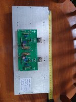
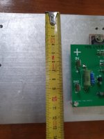
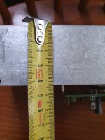
View attachment 1427592View attachment 1427593View attachment 1427594
祝你今天過得愉快
斯皮羅斯
Does this thing also work well on AB class?
Hope could email me the Gerbers yingtsoh2017@gmail.com
thanks
Hi Spiros, could you help me with the Gerber .. can it be used with any other alternative transistor directly..?
my email id Prasi.hobby@gmail.com
my email id Prasi.hobby@gmail.com
@prasi79,
You should ask the Mods to remove your email from public sight. Private message members directly instead.
You should ask the Mods to remove your email from public sight. Private message members directly instead.
I'm in the proces of assembling this P.S. design in order to feed some Class A mosfet amplifiers , operating at 1A per output device.
I'm using Sanken MP1620 / MN2488 darlington transistors simply because i have these in stock.
So far i have tested and adjusted the output voltage without load and works okay so far .
Just wondering about what voltage drop across the darlington will be optimal for proper regulation while keeping the dissipation safely
In relation to the heatsink i'm using right now ... should i measure a certain temperature on the heatsink ?
Thank you in advance
Do you know the thermal impedance of the heatsink? Or size information?
That is key to know the temp rise.
Jan
That is key to know the temp rise.
Jan
The voltage drop is around 3 volts. If the transformer secondary voltage is 28VAC, you will get 28 X 1,41 - 3V = 36VDC maximum at 2A quiescent current. As far as the heat sink, it depends on the current you want to flow through it.
Thank you for the fast replies!
Just took a decent heatsink .. will provide size details later today . But given the 3 Volts drop I assume it will do it's job adequately.
More later
Just took a decent heatsink .. will provide size details later today . But given the 3 Volts drop I assume it will do it's job adequately.
More later
First attempt ,
I cannot dial in the 3 Volt drop across the darlington under load .
8 Volt is minimum 🤔
Also , I measure 250mV ripple at both POS. & NEG. rail .
Perhaps the two 7500 uF caps are not sufficient ? Well let me check out tomorrow and grab some higher capacitance value .
Maybe I need CRC as well. It's real nothing more than a bridge and a cap pair right now .
How did you try to do that?I cannot dial in the 3 Volt drop across the darlington under load
Note that the input ripple is high(er) at the input and the 3V needs to be present from the lowest point on the input voltage, the lowest point of the ripple voltage. If the average voltage measured on an average-responding multimeter is 20V, with 4V p-p ripple, your minimum across the darlington should be 5V measured on an averaging-responding multimeter to respect the 3V minimum.
Also, what was the load current for those ripple values?
That heatsink seems adequate for 6W-ish max dissipation.
Jan
Last edited:
Hello Jan , by turning the trimpot meant to adjust the output voltage
Load current was exactly 1A
Load current was exactly 1A
So what is the problem? 'Can't dial in' doesn't give any info as to what could be the issue.
Is the control range of the trimpot not enough?
Is the input voltage too low to get to the required setpoint?
If you want help you should be less cryptic.
Jan
Is the control range of the trimpot not enough?
Is the input voltage too low to get to the required setpoint?
If you want help you should be less cryptic.
Jan
This circuit works fine in my 3 class A amps. My heat sinks are a little wider than yours: 48cm X 16cm X 5cm. It gets hot with a 2A QC, but the ripple is just 2 to 6 mV.
The multiturn trimpot adjusts the desired voltage 3 volts below the secondary one. I used 4 X 15000uF smoothing caps before that circuit, just after the rectifying bridge. You can see the circuit board at post #64. Try to lower the 1K5/5W resistor to 1K. What is the output of your trafo secondary, and how many volts do you need for your amp?
The multiturn trimpot adjusts the desired voltage 3 volts below the secondary one. I used 4 X 15000uF smoothing caps before that circuit, just after the rectifying bridge. You can see the circuit board at post #64. Try to lower the 1K5/5W resistor to 1K. What is the output of your trafo secondary, and how many volts do you need for your amp?
- Home
- Amplifiers
- Power Supplies
- Dual rail power supply for class A amplifiers