Anyone ever consider learning how to mod dac boards and maybe replace the MCU with an Arduino (or similar)?
No reason to give up on a mostly good dac, even if money was refunded.
I've done it with my AK4495 (Weilang ?) DAC board. I replaced the 8051 / LCD1602 control board by an Arduino and some level shifters. Arduino steer the AK4118 via I2C and AK4495 via SPI. It also add encoder and IR control.
Software is documented, (but it's a beginner software....) hardware much less...
AIM65,
Good for you! Don't know why so many people seem to be intimidated by the prospect of taking control via I2C and or SPI.
Good for you! Don't know why so many people seem to be intimidated by the prospect of taking control via I2C and or SPI.
Anyone ever consider learning how to mod dac boards and maybe replace the MCU with an Arduino (or similar)?
No reason to give up on a mostly good dac, even if money was refunded.
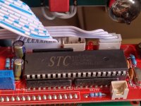
I replaced the STC with the Atmel MCU. With I2C, I have full control over AK4497 and AK4118. Of course with the remote control. No need for an Arduino, Atmel works satisfactorily.
...No need for an Arduino, Atmel works satisfactorily.
Sure. That's a good solution too.
Okay, then. For those that have solved the MCU control problems, are you helping the other guys who don't know how?
Okay, then. For those that have solved the MCU control problems, are you helping the other guys who don't know how?
My knowledge is not perfect. As far as I know, I'm capable of helping. Manufacturers have many variants for AK4497, I only know only my board in detail.
dd16,
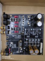
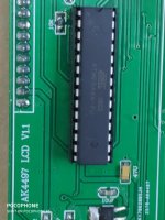
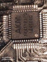
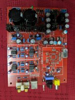
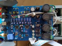
this is my 4497 dual board and mcu chip
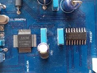
I see Atmega8A. I assume that the panels in the picture are connected to each other by a flat cable. I think it would be possible to create a program to check which inputs are really active.
The thing to do is trace where signals go with a low voltage continuity checker, such as is built into many DVMs. Write down the part numbers on all the ICs an download the data sheets. Sketch out a schematic of the interconnections you find. It might take a few hours, but not a few days.
If there is a CPLD on the board that could be a complication since what it does depends on how it is configured, not necessarily a deal killer though. If you find one, get the part number and trace out what goes through it. In the worst case, it could be bypassed.
There are only a few I2S and MCLK signals needed from a USB board or BT board. SPDIF requires a SPDIF receiver which in turn outputs I2S and MCLK signals needed by the dac chips.
The dac chips will have I2C address pins connected to V+ or to ground. Those pins determine the I2C control address of each dac chip.
Armed with a schematic and address pin configuration, it is often pretty straightforward to write a short MCU program to do what needs to be done. Downloadable libraries are often available to help with I2C bus logic, optical receiver decoding, and display driving.
It can all be done at the hobbyist level if one is willing to spend the diy time. First time around may take awhile, but it gets easier every time after that.
Last edited:
dd16
The pictures are not completely clear. I can't see which chips are on the board. I assume that the input to the AK4497 is made with a multiplexer that switches the input between the AK4118 and the XMOS (or Amanero). Attempt to replace ATmega8A.
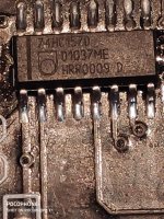
AK4118 is the SPDIF receiver. The 74HC157 is a logic chip used to select the I2S input source for the dac chips. Means no CPLD found, so probably easy going to diy.
Exactly, Mark. Blade only needs to know that 74HC157 switches between AK4118 and XMOS module. Something must be happening on pins 1 or 15 of 74HC157 when switching input from AK4118 to XMOS. If there is no change, the MCU is not working properly, otherwise the 74HC157 and XMOS connection should be checked.
dd16
Hi
You have certainly 2 HC157 on the board because you have 3 sources: AK4118, USB and Bluetooth. So, there’re probably cascaded. If not, input selection is made through one HC157 per AK4497 and with the second input of the AK4497. But it’s quite unlikely because this second input is DSD/TDM only.
Pin 15 of the two HC157 are probably grounded: they need to be always active.
Question is: who drive their select pin (1)? It could be the external MCU, through the connector or the AK4118 which has 8 gpio port, manageable through serial. As the HC157 are close the 4118 , using the 4118 GPIO allows to simplify the pcb layout.
You could probe pin 1 of the two HC157 with pin 12,14,15,16,17,18,19 and 20 the 4118.
Just to scope the research before deep diving into the pcb, I would also check if 4497 running in pin control mode (hardware) or in register control mode (software). In hardware it’s a standalone chip which don’t need a mcu to run, in serial it has to be initialized by a mcu. Check pin 14 (psn), Low is register, High (3.3v) is pin. If you’re in hardware mode that will limit the scope of your research and ease problem resolution.
Last edited:
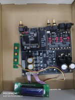
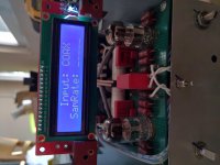
This is my MCU, maybe like you. You replaced Atmel, it works with LCD? Select input and volume? Did you rewrite the software for the MCU?I replaced the STC with the Atmel MCU. With I2C, I have full control over AK4497 and AK4118. Of course with the remote control. No need for an Arduino, Atmel works satisfactorily.
Can you help me?
Attachments

Last edited:
I replaced the STC with the Atmel MCU. With I2C, I have full control over AK4497 and AK4118. Of course with the remote control. No need for an Arduino, Atmel works satisfactorily.
This is my MCU, maybe like you. You replaced Atmel, it works with LCD? Select input and volume? Did you rewrite the software for the MCU?
Can you help me?
Attachments


This is my MCU, maybe like you. You replaced Atmel, it works with LCD? Select input and volume? Did you rewrite the software for the MCU?
Can you help me?
Yes, i have the same board. Atmel works with LCD and with the china remote. With remote i can setup AK4497 (select input, volume, sound, .... see pics). MCU can be Atmel or STC, but Atmel works better.


- Home
- Source & Line
- Digital Line Level
- Dual Mono DAC AK4490/AK4497