Looks fine as far as it goes - AD797 wouldn't be my first choice for I/V though. JFET input opamps tend to be more resistant to RF (very high frequencies come out of DAC chips) than bipolar ones, or use a CFB one.
Thanks. The circuit came from the datasheet of AD797, there is an example with AD1862 DAC what is almost the same with the AD1865. I will try another opamp, remove the capacitors, what EUVL suggested.
Honestly...this is exactly what you need:
Download and read Technics SLP-990 service manual schematic
TECHNICS SL-P990 Service Manual download, schematics, eeprom, repair info for electronics experts
download pcm 56, pcm61, ad 1860, ad 1865 datasheet.
They are all basically the same thing, except ad1865 has two ad 1860 in it.
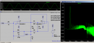
Build the Technics version of I/V converter.I did it in single ended topologies based on pcm56 for an older cd-player NEC cd-810.I also used the internal op-amp of that dac as vref for an external op-amp...It's your choice here! Here you have the whole discussion on how to use a fairly low noise fet input op-amp(opa2132) and a very fast and powerful bipolar op-amp for the second op-amp(Lm6172) including its own sub-base mods , thus circumventing each op-amp's weakness and using their best attributes in the compound op-amp circuit:
https://www.diyaudio.com/forums/digital-source/338152-nec-cd-810-revival-mods.html#post5809151
And here's the simulation made with the precious help of EUVL simulation model:
https://www.diyaudio.com/forums/ana...amuel-groners-super-opamp-18.html#post5810841
I can guarantee that the result can only be awesome by following Technics (some say Sandman's stolen )notes.
Believe it or not this was the most advanced I/V circuit ever to be manufactured by a company and i personally doubt that any other solution is more faithful to the sound reproduction.
As you can see it's not useful just for i/v stages as Technics used it in every single analog stage in their best players up to SLP-1000 and SLP-2000 model.
Just be warned that this I/V stage doesn't have any musicality of it's own, you only get out of it with the music you put in it!
Thanks ,the Technincs schematic was to complex for me. The circuit in Ltspice model is the same? This is what I need?
Well...electronics is a complex science...You first need to read all the documents and put them together in your head, see the similarities ad the differences and work out a solution for your dac.I'm sure that your dac is using the input op-amp of ad1865 , it's also using an output double op-amp which looks like an opa2134(identical pinout with opa2132), so you only need one more double power op-amp like lm6172 on a small board with those resistors and capacitors and some wiring...
I had. AD1865 outputs paralleled, 100R I/V resistor, 1,5k souncard input for load, THD was about 0,003% as also in datasheet.Yeah its speculation based on a little exploration I did after seeing the poor measurements (on ASR) of a Schiit multibit DAC using AD5547. Turns out that the usual kind of R2R DAC has extreme sensitivity to the output voltage in order to get high linearity. Has anyone done any THD measurements with 200R as passive I/V? I'll follow your links a little later.
That means 0.2v output, right?I had. AD1865 outputs paralleled, 100R I/V resistor, 1,5k souncard input for load, THD was about 0,003% as also in datasheet.
The Technics Class AA, or Sandman Class S, is not really class A.
(Valve and Transistor Audio Amplifiers, John Linsley Hood, Page 179)
It only serves to reduce load on the voltage amplification opamp.
The output stage is still Class B and suffers from crossover distortion.
This is then suppressed by another opamp.
Suppression is never the same as elimination.
On top of that, modern opamps such as OPA1656 will have no problem driving line-level loads.
So for me at least an OPA1656 biased into Class A is a better solution than the all that complication.
Depends on what the front end before the DAC does (OS with a digital filter or not), a reconstruction filter may not be necessary.
One can argue whether an (active) opamp gyrator is sonically better than a passive inductor.
More complicated it is in any case.
I am personally not a fan of complicated filters.
I rather have oversampling and try to do it right.
The circuit in post#1 is not an IV.
It is merely a first order RC filter after DAC voltage output, followed by a voltage gain stage.
If you wish to use voltage output anyhow, you can take a look at our discrete 3rd order Sallen Key filter for the AK4495.
SD Card Memory FLAC/WAV 192/24 player - ESS crescendo II - AK4495 - DV20A
Till today, we have not found a better solution than the CEN IV or SEN IV, not even multiple AD844s in parallel and in open loop.
(other than perhaps pure passive IV with < 100R).
The performance comes simply from Kirchoff's law and not by any feedback loop or whatever.
There will be an updated version later this year, but it still uses Toshiba JFETs and floating power supplies.
It does have some advantages, but is on the other hand more complicated.
Patrick
The Technics Class AA, or Sandman Class S, is not really class A.
(Valve and Transistor Audio Amplifiers, John Linsley Hood, Page 179)
It only serves to reduce load on the voltage amplification opamp.
The output stage is still Class B and suffers from crossover distortion.
This is then suppressed by another opamp.
Suppression is never the same as elimination.
On top of that, modern opamps such as OPA1656 will have no problem driving line-level loads.
So for me at least an OPA1656 biased into Class A is a better solution than the all that complication.
Depends on what the front end before the DAC does (OS with a digital filter or not), a reconstruction filter may not be necessary.
One can argue whether an (active) opamp gyrator is sonically better than a passive inductor.
More complicated it is in any case.
I am personally not a fan of complicated filters.
I rather have oversampling and try to do it right.
The circuit in post#1 is not an IV.
It is merely a first order RC filter after DAC voltage output, followed by a voltage gain stage.
If you wish to use voltage output anyhow, you can take a look at our discrete 3rd order Sallen Key filter for the AK4495.
SD Card Memory FLAC/WAV 192/24 player - ESS crescendo II - AK4495 - DV20A
Till today, we have not found a better solution than the CEN IV or SEN IV, not even multiple AD844s in parallel and in open loop.
(other than perhaps pure passive IV with < 100R).
The performance comes simply from Kirchoff's law and not by any feedback loop or whatever.
There will be an updated version later this year, but it still uses Toshiba JFETs and floating power supplies.
It does have some advantages, but is on the other hand more complicated.
Patrick
Well... here are your own words :
https://www.diyaudio.com/forums/ana...amuel-groners-super-opamp-18.html#post5810812
The next post was simply showing YOUR OWN SIMULATION MODEL AT WORK on the right circuit .
It was much lower distortion than two of the nowadays best op-amps on the market in parallel and you and Jan didn't like it so
JAN TRIED TO DIVERT that discussion on Sandman's patent...which was debatable too, and that is what a high end seller will always look to do when finding resistance:
Start Debating...
You were so furious after i have used your own simulation to debunk your myths that you and your partner completely abandoned that topic and started to gather audience for buying those Groner's circuits on other channels.
You can't f...measure -180db THD!
I wouldn't buy those circuits in a million years as they use the most expensive op-amps on the market with no additional gain to the original 30 years old Technics circuit.
Nor i would ever bias an op-amp externally in class A ..I'd rather make a class A discrete preamp than overheating a 500mw case.
So on one channel you advise people to buy class A moded circuits, actually yours , on the other channel you try to say that ultra low distortion is ultra low distortion only if it has your own friends name on it...
Well sorry my friend, but that is not credible !
And by the way...i haven't been on this forum for 6 months since our last chat and all i can find is actually that you and Jan convinced more and more people to buy your "credible" circuits...but opening other channels...
You don't like people disagreeing with you!
You are afraid of people NOT agreeing with you and i have the proof for that!
By the way...Sandman lost that trial against Technics-Matsushita!
Sandman v. Panasonic UK Limited, Matsushita Electric Industrial Co Ltd | (1998) 21(4) IPD 21038 | England and Wales High Court (Patents Court) | Judgment | Law | CaseMine
Last edited:
The circuit in post#1 is not an IV.
It is merely a first order RC filter after DAC voltage output, followed by a voltage gain stage.
Sorry you are absolutely right. The name of the 2nd attachment is misleading. I've edited the #1 post. This is the current, unmodified output stage of the DAC board in voltage mode.
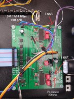
Hi! did you already have this dac running? I have the same board here and runned it with a tube i/v (lampizator style). Did some tweaks like lift the sj pins and used I-out, etc. After a while I ditched the project, I couldn't get the SQ even close to my single deck DDDAC.
Attachments
Hi,
I have this DAC board, but I did't modified it. Thanks to Democles I've built another AD1865 DAC. I wasn't sure that after the modification of the DiyINHK DAC will be better than the factory version.
If I understood, well you have same experience? After the modification the sound quality didn't improve too much?
- Home
- Source & Line
- Digital Line Level
- Dual Differential AD1865 - Output stage question