Hi,
I have this DAC board, and I want to improve the output stage. My goal is a bigger sound stage, better separation between the instruments..

For the first step I don't want to spend too much money (for example output transformers, with vacuum valves etc) therefore I'm thinking about using the same voltage output of the dac, but I want to use better quality and through hole components, and if it's exist, a better circuit.
Any suggestion, schematic etc. would be appreciated. Because I'm not an expert I want to keep it simple 🙂
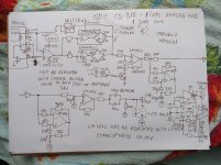
I tried reverse engineering of the output stage of the dac board.
View attachment IV_Schematic.pdf*
* It's not an I/V converter, this is the output stage of the dac board.
Is it recommended to using separate power source for the analog part of the DAC chips, and for the output stage? Because currently it's common.
I have this DAC board, and I want to improve the output stage. My goal is a bigger sound stage, better separation between the instruments..
For the first step I don't want to spend too much money (for example output transformers, with vacuum valves etc) therefore I'm thinking about using the same voltage output of the dac, but I want to use better quality and through hole components, and if it's exist, a better circuit.
Any suggestion, schematic etc. would be appreciated. Because I'm not an expert I want to keep it simple 🙂
I tried reverse engineering of the output stage of the dac board.
View attachment IV_Schematic.pdf*
* It's not an I/V converter, this is the output stage of the dac board.
Is it recommended to using separate power source for the analog part of the DAC chips, and for the output stage? Because currently it's common.
Last edited:
I don't have experience with this particular chip but seems to me you're likely limited by the on-chip opamps when you choose voltage output. Better instrumental separation will likely come from a discrete I/V, also maybe add a passive LP filter.
Could you recommend any schamatic to using the current output of the chip?I don't have experience with this particular chip but seems to me you're likely limited by the on-chip opamps when you choose voltage output. Better instrumental separation will likely come from a discrete I/V, also maybe add a passive LP filter.
Some DSP will widen the sound stage - just subtract a little of each channel from the other. Don't overdo it. This is the opposite of narrowing the soundstage by mixing the channels together slightly.
Fiddling with the DAC circuitry won't do anything useful if its currently working.
Fiddling with the DAC circuitry won't do anything useful if its currently working.
Could you recommend any schamatic to using the current output of the chip?
If you go to my lingDAC thread there is a schematic of the I/V and filter board which is a discrete design. There might be some minor compatibility issues to figure out as I've not looked into the AD1865 DS in great detail. I did notice its not what I'd call a true current output DAC, it has an output impedance below 2kohm, fairly typical for a R2R. I'm not sure that the output impedance is constant, you'd need to check if you want to use the passive filter. As its not hi-Z output the filter (CLCLC) in my schematic might need a little bit of tweaking for the correct frequency response. Or you could omit it entirely. Next you should check the output voltage compliance range for the AD1865 to ensure the I/V's input voltage is compatible with it. The other thing to check is offset/bias currents from the DAC chip- the DAC my circuit's designed for is a unipolar output type (maximum 1.2mA).
lingDAC - cost effective RBCD multibit DAC design - you want the middle one of the three .pdfs.

The other thing to check is offset/bias currents from the DAC chip- the DAC my circuit's designed for is a unipolar output type (maximum 1.2mA).
lingDAC - cost effective RBCD multibit DAC design - you want the middle one of the three .pdfs.
According to the datasheet, AD1865 in current output configuration mode has bipolar output +/-1mA.
The question is the differential mode. Or is it possible to using the I_Out_R from one DAC chip and I_Out_L from the other one?
Yes, I think the best way is to do I/V on both phases.
Having looked over the DS a bit more, I'm not totally convinced discrete I/V is the best solution now. That's because I'm seeing no output compliance voltage spec for the AD1865 - meaning it could be insanely sensitive (in distortion performance terms) to the output voltage the output pin is held at. Perhaps better to use an external high speed opamp (AD811, AD815 or AD8017 would be my first choices). At least with an opamp you'll have at worst a few mV output voltage uncertainty. With a discrete stage it'll be at least 10X worse than that unless you design a servo for it.
Having looked over the DS a bit more, I'm not totally convinced discrete I/V is the best solution now. That's because I'm seeing no output compliance voltage spec for the AD1865 - meaning it could be insanely sensitive (in distortion performance terms) to the output voltage the output pin is held at. Perhaps better to use an external high speed opamp (AD811, AD815 or AD8017 would be my first choices). At least with an opamp you'll have at worst a few mV output voltage uncertainty. With a discrete stage it'll be at least 10X worse than that unless you design a servo for it.
> I'm seeing no output compliance voltage spec for the AD1865 -
> meaning it could be insanely sensitive (in distortion performance terms) to the output voltage the output pin is held at
Your speculation ?
Seems enough people have tried 200R passive IV.
Why do we need I/V stage for AD1865
DAC End 2 - the AD1865N-K with single ended vacuum output stage
Audio DAC with AD1865
(Not that I would use one myself, but I definitely would not use an opamp IV.)
Cheers,
Patrick
Yeah its speculation based on a little exploration I did after seeing the poor measurements (on ASR) of a Schiit multibit DAC using AD5547. Turns out that the usual kind of R2R DAC has extreme sensitivity to the output voltage in order to get high linearity. Has anyone done any THD measurements with 200R as passive I/V? I'll follow your links a little later.
Some people are using much lower value I/V resistor. I'ts possible to go down until 58R. According to their experience the sound quality improved using lower value i/v resistor.
What is the advantage of the opamp i/V conversion compared to passive i/v resistor?
What is the advantage of the opamp i/V conversion compared to passive i/v resistor?
Easy to do. Saves cost (already on the chip).
Low Zin and Zout.
Patrick
Now I've found Zen->Cen->Sen I/V converter. Is it possible to using with this differential DAC? Which one, and how?
Some people are using much lower value I/V resistor. I'ts possible to go down until 58R. According to their experience the sound quality improved using lower value i/v resistor.
That would be my expectation, though the DAC's sensitivity to power supply goes up as the passive I/V resistor goes down as there's more gain involved to get back to signal level.
What is the advantage of the opamp i/V conversion compared to passive i/v resistor?
The primary advantage is that the DAC's been designed to drive into a virtual short. Linearity (from the DAC) improves as the output voltage isn't swinging very much with signal. Downside of course is you get the opamp's (and power supply) sound signature which in my experience is great bass but not quite so pristine HF.
Could you check please this schematic? Or need to use the other I_out pin of the DAC chips?
Looks fine as far as it goes - AD797 wouldn't be my first choice for I/V though. JFET input opamps tend to be more resistant to RF (very high frequencies come out of DAC chips) than bipolar ones, or use a CFB one.
We tried this with a PCM1704 and a JFTE opamp:
Any project with PCM1704
Huge distortion until we removed C7, C8.
So be warned.
Patrick
Any project with PCM1704
Huge distortion until we removed C7, C8.
So be warned.
Patrick
Honestly...this is exactly what you need:
Download and read Technics SLP-990 service manual schematic
TECHNICS SL-P990 Service Manual download, schematics, eeprom, repair info for electronics experts
download pcm 56, pcm61, ad 1860, ad 1865 datasheet.
They are all basically the same thing, except ad1865 has two ad 1860 in it.
Build the Technics version of I/V converter.I did it in single ended topologies based on pcm56 for an older cd-player NEC cd-810.I also used the internal op-amp of that dac as vref for an external op-amp...It's your choice here! Here you have the whole discussion on how to use a fairly low noise fet input op-amp(opa2132) and a very fast and powerful bipolar op-amp for the second op-amp(Lm6172) including its own sub-base mods , thus circumventing each op-amp's weakness and using their best attributes in the compound op-amp circuit:
https://www.diyaudio.com/forums/digital-source/338152-nec-cd-810-revival-mods.html#post5809151
And here's the simulation made with the precious help of EUVL simulation model:
https://www.diyaudio.com/forums/ana...amuel-groners-super-opamp-18.html#post5810841
I can guarantee that the result can only be awesome by following Technics (some say Sandman's stolen )notes.
Believe it or not this was the most advanced I/V circuit ever to be manufactured by a company and i personally doubt that any other solution is more faithful to the sound reproduction.
As you can see it's not useful just for i/v stages as Technics used it in every single analog stage in their best players up to SLP-1000 and SLP-2000 model.
Just be warned that this I/V stage doesn't have any musicality of it's own, you only get out of it with the music you put in it!
Attachments

Last edited:
- Home
- Source & Line
- Digital Line Level
- Dual Differential AD1865 - Output stage question