Thanks for the answer. About the linux kernel modules. Wouldn't it be a possibility to blacklist the modules in /etc/modproble.d/blacklist.conf? Or maybe a blacklist-nadja.conf? Well, I'll rest on the topic until I can test in practice.
Thanks for the answer. About the linux kernel modules. Wouldn't it be a possibility to blacklist the modules in /etc/modproble.d/blacklist.conf? Or maybe a blacklist-nadja.conf? Well, I'll rest on the topic until I can test in practice.
I'm sorry, I'm unable to answer your question. Maybe Xav will when he has some spare time.
We're getting ready to release the software, so I'm posting a couple of screenshots of the IIR filtering mode (which is coming on top of the FIR Engine mode described earlier). If there's enough interest, we'll add gradually more meat into the software 😉 (How about a subtractive with Lipshitz-Vanderkoy delays? 🙂 )
Well for now it's a classic IIR. The input section:

So this is where it's all starting. The user supplies a stereo pair of inputs, and Najda transforms this pair into 4 separate signals (L, R, SUM, DIFF) with their own processing path.
In the above screenshot, only the Left channel processing path has something relevant in it (i.e. the other channels are unprocessed).
Processing begins with a 2500-sample delay (max 8191) followed by a -4 dB gain, and a set of 3 second order sections.
The second order filters that you have here are the ones that all of you have used: peaking/low shelf/high shelf. The peaking filter has of course adjustable Q factor and the shelves have adjustable slope.
I'm often asked: How many filters per channel do I get?
Well, Najda doesn't use a fixed processing path. You can see on the screenshot above the ADD SECTION button. Click this button and the application will add a filter to the selected channel. Click this button as many times as you like, there's no limit (well we've set a limit of ten for the sake of wisdom, but we could extend this to virtually any number).
Now an important point: you might remember that the monitor tab shows the DSP load. It's the user responsibility to make sure that the processing he's devising doesn't overload the DSP. In other words, while the user is adding filters, he should check the DSP load meters and make sure they stay below 100%.
This flexibility feature allows distributing the processing power where your system needs it instead of allocating a fixed number of filters to some channels you might not even use.
The next tab is the output processing.

On the far left, you're routing the signal. This means that you select one of the 4 processed channels we talked about earlier (Left, Right, Sum or Diff).
Routing is followed by a Pregain, then a group of 3 IIR blocks.
First block is the LowPass filter.
Second block is the HighPass filter.
Supported filters are
- Butterworth 6/12/18/24/36/48 dB/oct.
- Bessel 12/18/24/36/48 dB/oct.
- Linkwitz Riley 12/24/36/48 dB/oct.
Butterworth cut-off frequency is where the response is -3dB, as usual.
For Linkwitz-Riley, we also use the classic cut-off at -6dB.
Bessel filters are phase match - so there's no fixed dB number at cut-off. Instead, a low-pass and a high-pass with same orders and cut-off frequencies will have phases that are a multiple of 90 degrees apart at design frequency.
The cross-over design follows the same principle as the filter section I described earlier: a by-pass doesn't use processing power, and the higher the filter order, the more processing power it burns (so always check the DSP load meters!).
The crossover block is followed by the EQ block (peaking/shelves) which is identical to the one on the input processing tab.
Then you get the PostGain, the channel polarity invert and the output delay (4095 samples max).
As a quick and dirty example, here's what you can read on channel 6:
- Routing is the Diff signal
- Pregain -4dB
- Low pass F=1000 Hz Bessel 36dB/oct
- High pass F=100 Hz Linkwitz-Riley 48dB/oct
- Only 1 EQ section(it's a good driver 😉 ) which is a peaking filter with F=235Hz, 6dB gain, and Q factor 3.4.
- 3dB PostGain
- Polarity inverted (don't ask why 😛)
- 2345 samples output delay, which is 24.427 ms at 48 kHz sampling frequency.
Of course, the whole processing can be viewed on the graph tabs.
Last edited:
Can you test out the software without Nadja ?
Also a question about controlling the volume when the.analouge volume control option is installed:
Is there any way to send a signal, digital or analouge to Nadja (or is it THE Nadja?) , in order to have a master volume control on all analouge channels?
I have a modded H&K AVR7300 where I would like to fit Nadja between pre out select (ie before volume controls) and main in (to power amps)
Can you test out the software without Nadja ?
Yes the application will be available for download sometime this weekend on the website. Note however that all the windows that allow communicating with Najda (monitor, output level settings, preset management etc) are accessible only when the board is connected.
Also a question about controlling the volume when the.analouge volume control option is installed:
Is there any way to send a signal, digital or analouge to Nadja (or is it THE Nadja?) , in order to have a master volume control on all analouge channels?
I have a modded H&K AVR7300 where I would like to fit Nadja between pre out select (ie before volume controls) and main in (to power amps)
I'm not sure I understand this question.
You can control Najda's volume by pressing the volume push-buttons or using a remote controller.
Now if you're thinking of controlling the volume via a signal from another device, I'm afraid this is not possible without some tweaks.
You answered perfectly!
The AVR uses a volume IC chip that is controlled by a 24 bit word, bitbanged into with a sync clock.
I could always take this signal to a MCU and convert to pulses for the up/down button interface. some tweaking, but doable.
My thinking was if there was fex a control voltage input too.
The AVR uses a volume IC chip that is controlled by a 24 bit word, bitbanged into with a sync clock.
I could always take this signal to a MCU and convert to pulses for the up/down button interface. some tweaking, but doable.
My thinking was if there was fex a control voltage input too.
You answered perfectly!
The AVR uses a volume IC chip that is controlled by a 24 bit word, bitbanged into with a sync clock.
I could always take this signal to a MCU and convert to pulses for the up/down button interface. some tweaking, but doable.
My thinking was if there was fex a control voltage input too.
No there's no volume control input. That's unfortunate for you 🙂
The idea of generating pulses could make it, but there's a little issue however: when you turn on Najda, it sets the volume to what it was when you turned it off last time.
Your pulse strategy will then need to set the volume to a known value (for example volume min) then send the amount of pulses required to reach the value coded in your AVR's 24-bit word. (unless you can make sure that Najda and the AVR never get out of sync).
Well, that's a lot of work for a volume command. What's the problem with using just the push-buttons or the remote instead of controlling the volume via your AVR?
If it's about using the AVR remote controller - and provided that it's NEC compatible - you could achieve that by requesting Najda to respond to volume changes from your AVR's controller.
Hi Nick
About the connectors:
I think it would be good if you could attach the most necessary (or complete) molex-connectors of the board to the package.
You can buy the connectors in large quantities at low prices. We must each pay a multiple price.
What do you think about?
Best regards
Indemini
About the connectors:
I think it would be good if you could attach the most necessary (or complete) molex-connectors of the board to the package.
You can buy the connectors in large quantities at low prices. We must each pay a multiple price.
What do you think about?
Best regards
Indemini
Hi Nick
About the connectors:
I think it would be good if you could attach the most necessary (or complete) molex-connectors of the board to the package.
You can buy the connectors in large quantities at low prices. We must each pay a multiple price.
What do you think about?
Best regards
Indemini
Hi Indemini,
It's not clear to me what connectors you're referring to.
There isn't any Molex branded connector on the board.
The board comes with all connectors except the 2 I2S expansion port pin-headers. These are the most standard headers you can find, and you get a handful of these for some pocket change. These headers were left unpopulated so that you can solder in the connector that you like (for example RJ45 for I2S stereo input).
Now if you were referring to connecting cables, then it's not really practical for me as I cannot guess what LCD display you're going to get (they don't have always same pin layout). I can't guess neither where you're going to place the push-buttons, the leds and the IR sensor - and this is determining the required cable length.
As a matter of fact, I'm throwing in a few 8-pole flat cables with the boards shipped (while stock lasts). Their use is not compulsory as you might have a better system for wiring your equipment (so in this case keep your system and chuck away the supplied flat cables 😉 )
I don't know if I've answered your question. If something is not understood, please drop me a another line.
Nick
Hi Nick,
I have read through much of this thread, albeit not all, but did not see any reference to mic input and any dsp functions including a mic. Is there any function with this board for mic? (rta, driver time alignment, etc)
Thanks
I have read through much of this thread, albeit not all, but did not see any reference to mic input and any dsp functions including a mic. Is there any function with this board for mic? (rta, driver time alignment, etc)
Thanks
Last edited:
Did some additional thread reading, now understand no measurement capability or auto tune items are included with najda.
Last edited:
Some tips for those assembling a unit with Najda DSP board (as a beta tester I had early access to one).
The main parts you will need are:
The project documentation is very good. I highly recommend that you read it through at least once before you make any attempt at assembly.
The component legend printed on PCB does not clearly show the pin markings and IDs, so you must make use of the supplied diagram in Appendix_B_Pinning_Power_Supply.pdf.
Your power supply must comply with the specification described in the Najda_Startup_Guide.pdf.
The headers on the board are of the type with 0.79mm square pins and 2.54mm spacing. Essentially, you need a plug to connect onto it (you could solder wires directly onto these pins, but I would not recommend this, as it is messy, and the exercise would increase the possibility of damaging the electronic ports through ESD). Here are some options: (1) buy some cables with pre-crimped plugs at the ends (2) assemble your own, for which you'd need to select the correct plug bodies and crimp contacts, as well as a suitable crimp tool (3) use old-school ribbon cable and ribbon cable connectors (IDE-style); these you can crimp in a bench vise.
LEDs and pushbuttons: Connecting up the LEDs is straight-forward. The Najda_Startup_Guide.pdf describes wiring very well. It is the same for the pushbuttons (it is not matrixed like a regular keypad, that's why I'm not calling it a keypad).
IR sensor: match the header pin allocations vs the IR sensor's pin-outs and connect accordingly.
IR remote control: the remote I used belonged to a old TV card. Check that the remote you use has a sufficient amount of buttons to accommodate the functions of the Najda system. My own, I found, uses an NEC protocol. It is very easy to set up; just find the remote setup in the menu and follow the prompts.
LCD display: This must be of the type that has 2 rows of 16 alphanumeric characters, and must have a parallel data interface complying with the HD44780 driver chip. It must also have back lighting. The one I got has very low efficiency back lighting, and I would appreciate recommendations for better-performing units from you guys. I chose my LCD display primarily on the basis of pin-to-pin compatibility, so I could plug directly into the Najda DSP board with a 16-way ribbon cable. Note that other compatible LCDs may not have directly-corresponding pins, and therefore cannot plug in directly, without rerouting the wires. Also - very important - note which side of the LCD display connector is the right side up. On my own LCD, the pins are read from the front. But do check what is correct for your own LCD. In order to plug in correctly, I had to use a 90 degree header, because there would not be sufficient space next to the LCD module to plug from the front. Again, there are other numbering schemes, so check your own. I would have loved to use a VFD (plasma) display, but compatible models are rare and expensive. Please share if you find any at a good price.
Startup: Najda DSP starts up in standby mode, so once power is applied there are no signs of life*. To get it going, push the STANDBY button. Then the LCD back light will turn on, the LCD will display the firmware version, and one or other LED will flash momentarily.
PC installation of the Najda configuration application: the USB driver software is available from here D2XX Direct Drivers. I opted to use the executable installation download. Although the driver got installed by this application, the Najda software would not run until the driver was fully configured. This required the Najda DSP to be connected to the PC via USB cable.
Saving your configuration: After making any adjustments to the system variables (volume/bass/treble/balance, etc. and programming), you need to set the system into standby mode, during which process the settings/configuration will be permanently stored in memory.
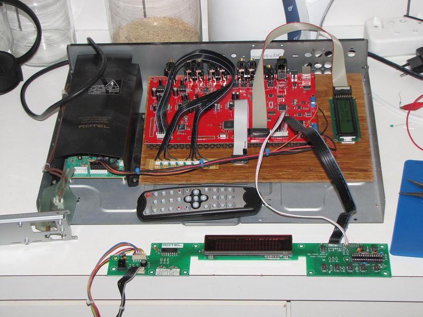
That's all I can think of, for now. Good luck! Here are some photos of my own setup in an intermediate (test) phase. (I hacked the chassis on of an old Rotel DVD player, and used the existing power supply and push buttons).
*Actually, to be more correct, it powers up in the same condition as it powered down. But the manufacturer's instruction is that the user should always switch to standby at the end of a session (and do not power down directly), due to some internal operations that need to happen at the end of the session.
.
The main parts you will need are:
- Najda DSP board
- a suitable enclosure
- a suitable power supply
- a suitable 2x16 LCD
- LEDs
- push-to-make pushbuttons
- infra-red sensor
- interconnecting cables with suitable plugs (more about that later)
- a USB cable
- an IR remote control
The project documentation is very good. I highly recommend that you read it through at least once before you make any attempt at assembly.
The component legend printed on PCB does not clearly show the pin markings and IDs, so you must make use of the supplied diagram in Appendix_B_Pinning_Power_Supply.pdf.
Your power supply must comply with the specification described in the Najda_Startup_Guide.pdf.
The headers on the board are of the type with 0.79mm square pins and 2.54mm spacing. Essentially, you need a plug to connect onto it (you could solder wires directly onto these pins, but I would not recommend this, as it is messy, and the exercise would increase the possibility of damaging the electronic ports through ESD). Here are some options: (1) buy some cables with pre-crimped plugs at the ends (2) assemble your own, for which you'd need to select the correct plug bodies and crimp contacts, as well as a suitable crimp tool (3) use old-school ribbon cable and ribbon cable connectors (IDE-style); these you can crimp in a bench vise.
LEDs and pushbuttons: Connecting up the LEDs is straight-forward. The Najda_Startup_Guide.pdf describes wiring very well. It is the same for the pushbuttons (it is not matrixed like a regular keypad, that's why I'm not calling it a keypad).
IR sensor: match the header pin allocations vs the IR sensor's pin-outs and connect accordingly.
IR remote control: the remote I used belonged to a old TV card. Check that the remote you use has a sufficient amount of buttons to accommodate the functions of the Najda system. My own, I found, uses an NEC protocol. It is very easy to set up; just find the remote setup in the menu and follow the prompts.
LCD display: This must be of the type that has 2 rows of 16 alphanumeric characters, and must have a parallel data interface complying with the HD44780 driver chip. It must also have back lighting. The one I got has very low efficiency back lighting, and I would appreciate recommendations for better-performing units from you guys. I chose my LCD display primarily on the basis of pin-to-pin compatibility, so I could plug directly into the Najda DSP board with a 16-way ribbon cable. Note that other compatible LCDs may not have directly-corresponding pins, and therefore cannot plug in directly, without rerouting the wires. Also - very important - note which side of the LCD display connector is the right side up. On my own LCD, the pins are read from the front. But do check what is correct for your own LCD. In order to plug in correctly, I had to use a 90 degree header, because there would not be sufficient space next to the LCD module to plug from the front. Again, there are other numbering schemes, so check your own. I would have loved to use a VFD (plasma) display, but compatible models are rare and expensive. Please share if you find any at a good price.
Startup: Najda DSP starts up in standby mode, so once power is applied there are no signs of life*. To get it going, push the STANDBY button. Then the LCD back light will turn on, the LCD will display the firmware version, and one or other LED will flash momentarily.
PC installation of the Najda configuration application: the USB driver software is available from here D2XX Direct Drivers. I opted to use the executable installation download. Although the driver got installed by this application, the Najda software would not run until the driver was fully configured. This required the Najda DSP to be connected to the PC via USB cable.
Saving your configuration: After making any adjustments to the system variables (volume/bass/treble/balance, etc. and programming), you need to set the system into standby mode, during which process the settings/configuration will be permanently stored in memory.
That's all I can think of, for now. Good luck! Here are some photos of my own setup in an intermediate (test) phase. (I hacked the chassis on of an old Rotel DVD player, and used the existing power supply and push buttons).
An externally hosted image should be here but it was not working when we last tested it.
An externally hosted image should be here but it was not working when we last tested it.
An externally hosted image should be here but it was not working when we last tested it.
An externally hosted image should be here but it was not working when we last tested it.
*Actually, to be more correct, it powers up in the same condition as it powered down. But the manufacturer's instruction is that the user should always switch to standby at the end of a session (and do not power down directly), due to some internal operations that need to happen at the end of the session.
.
Last edited:
Thanks Shaun for sharing your experience.
Just a quick update: users won't need to worry about the USB drivers, the installer will take care of that. Shaun was not quite lucky in the sense that the installer was not ready when he got his board so he had to install the USB drivers manually.
Talking about the installer, the application is now available for download:
Najda Under Control
Splendid work Shaun! I love Your publication. Not worrying about aesthetics. This is a school book example of beta testing. Many thanks, this kind of posts really helps to get the picture.
[...]the application is now available for download:
Najda Under Control
For Vista/Win7 users:
After downloading the file, right-click on it and select "Run as administrator" otherwise Windows will not let the package install the USB drivers.
Hi, congrats for that Nice build Charpak
Questions
- what is happening with 44.1 kHz signal ? I understand there is only one clock on board for 48kHz. Will Some samples get lost ?
- is the software ready now for external clock ? I would like to feed 2or 3 external DACs Ad1865 nos SRPP from raindrop hui but they are on master mode and not slave mode (anyway there are too much)
- my WaveIO USB SPDIF board upward has also it´s own clock, so that makes 5... Way too much ?
BR
Jean-Louis
Last edited:
How can you have multiple master clocks?Hi, congrats for that Nice build Charpak
Questions
- what is happening with 44.1 kHz signal ? I understand there is only one clock on board for 48kHz. Will Some samples get lost ?
- is the software ready now for external clock ? I would like to feed 2or 3 external DACs Ad1865 nos SRPP from raindrop hui but they are on master mode and not slave mode (anyway there are too much)
- my WaveIO USB SPDIF board upward has also it´s own clock, so that makes 5... Way too much ?
BR
Jean-Louis
Salut Jean-Louis,
Thanks for your kind words.
Nico
Thanks for your kind words.
It goes through the sample rate converter and is converted to the internal user selected sampling frequency, which is one of 48 kHz, 96 kHz or 192 kHz.Questions
- what is happening with 44.1 kHz signal ? I understand there is only one clock on board for 48kHz. Will Some samples get lost ?
No the soft is not ready yet for external clocking. That will be made available with a future release.- is the software ready now for external clock ? I would like to feed 2or 3 external DACs Ad1865 nos SRPP from raindrop hui but they are on master mode and not slave mode (anyway there are too much)
This is not a problem at all. If your board outputs SPDIF, then you simply plug it to Najda's SPDIF input. If it outputs I2S, then you can also connect it to Expansion port 1. See section I.6. in the manual for I2S wiring details.- my WaveIO USB SPDIF board upward has also it´s own clock, so that makes 5... Way too much ?
Nico
How can you have multiple master clocks?
You got it, that´s called Mexican Army🙂
What I realize now from Charpak´s answer as I am not the master of the clocks 😉:
- no problem with the WaveIO clock, signal will be resampled / reclocked upon arrival by Najda. I hope btw that SQ will not be damaged as frequencies are not multiple of 44.1, maybe I miss something ?
- I'll use Najda's clock temporarily as the master clock (*), and possibly the Najda's DACs
- I will then have to find a way to change AD1865 NOS SRPP boards to slave mode. And that is a challenge for me, to make sure not to destroy the PCBs ! Has someone done this previously ?
Charpak, thanks for your answer. I have discovered your work after turning around the MiniDSP nano digi 2x8.
I understand the benefits of Najda are 24/192 kHz compatibility and FIR. Any other advantages ?
BR
Jean-Louis
(*) my original idea was to steal the clock from one of the CS8414 on the DAcs board and feed it on the two other dacs and the Najda, but not sure if doable...
Last edited:
What are folk doing about the power supply?
I don't have anything suitable - Nick mentioned a Meanwell model NET-35B + that the switching frequency has to be above the audio band (usually are).
He uses a Skynet open frame but unlikely to find one with all voltages.
Update: My board has just arrived!!! Looks very nice.
I don't have anything suitable - Nick mentioned a Meanwell model NET-35B + that the switching frequency has to be above the audio band (usually are).
He uses a Skynet open frame but unlikely to find one with all voltages.
Update: My board has just arrived!!! Looks very nice.
Last edited:
- no problem with the WaveIO clock, signal will be resampled / reclocked upon arrival by Najda. I hope btw that SQ will not be damaged as frequencies are not multiple of 44.1, maybe I miss something ?
I wouldn't worry about SQ.
- I'll use Najda's clock temporarily as the master clock (*), and possibly the Najda's DACs
- I will then have to find a way to change AD1865 NOS SRPP boards to slave mode. And that is a challenge for me, to make sure not to destroy the PCBs ! Has someone done this previously ?
I had a quick look at AD1865 datasheet, and it doesn't seem to support I2S. I'm not sure whether we talk about the same chip though, the one I looked at is an obsolete part from AD with 18-bit resolution.
If that's the one, then you'll need additional glue logic if you want to hook these DACs to Najda on the expansion port.
Now I'm wondering: the boards that you have, how do you feed audio in them? If you can feed SPDIF, then you just plug your boards to Najda's SPDIF outs and it's done.
Charpak, thanks for your answer. I have discovered your work after turning around the MiniDSP nano digi 2x8.
I understand the benefits of Najda are 24/192 kHz compatibility and FIR. Any other advantages ?
Every single board is loaded with love and care 😉
What are folk doing about the power supply?
I don't have anything suitable - Nick mentioned a Meanwell model NET-35B + that the switching frequency has to be above the audio band (usually are).
He uses a Skynet open frame but unlikely to find one with all voltages.
Update: My board has just arrived!!! Looks very nice.
Glad to hear you got your board Steve!
Here's the datasheet of the power supply that I'm using (model SNP9021-1).
http://www.skynetpower.com.tw/pdf/SNP-902Series.pdf
These are the things that you should look at when selecting a switched power supply:
- Make sure it outputs all 3 required voltages +5V/+12V/-12V with sufficient current.
- Look at the line regulation. This one has +/- 1%, which is OK.
- Look at the switching frequency. You don't want a too low switching frequency as it could introduce noise in the audio band. In this datasheet, if you're looking at the switching frequency ripple (figure on last page), you can see that the ripple's fundamental frequency is about 33kHz (period of 3 10-us divisions) which for me is alright as I can't hear anything above 33 kHz for sure.
- Now something important about safety: prefer a model with a housing. Don't get an open-frame model like the one I use (I actually have a suitable housing that comes on top of the PSU).
- Home
- Source & Line
- Digital Line Level
- DSP Xover project (part 2)