if you click on it, it should expand to a reasonable size.
I actually thougth of that 😉 The only chip I managed to read from was the "AK4101A".
There was a cirrus something that was close but I couldn't figure it out.
I have been brainstorming a psu today that migth be a little overkill but.....😎
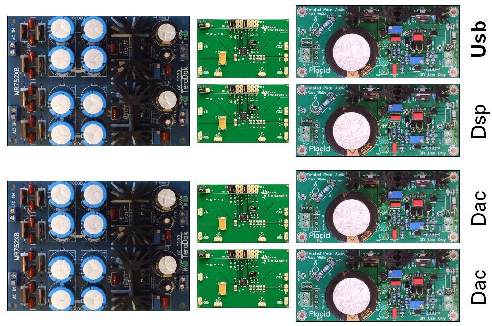
+/-12v missing in the picture.
I actually thougth of that 😉 The only chip I managed to read from was the "AK4101A".
There was a cirrus something that was close but I couldn't figure it out.
I have been brainstorming a psu today that migth be a little overkill but.....😎
+/-12v missing in the picture.
If you are trying to read the chip numbers it's obvious that some have been rubbed off 😉
Hmmmm, I thought that they looked a little bit to fussy, maybe my eye sight
isn't that bad after all. 😀
isn't that bad after all. 😀
If you are trying to read the chip numbers it's obvious that some have been rubbed off 😉
No mate, we don't rub off chip numbers here. Why the heck would we do that?

Cirrus and AKM use a white ink with a lot of contrast, other manufacturers use a darker ink. That's it all.
No mate, we don't rub off chip numbers here. Why the heck would we do that?
Cirrus and AKM use a white ink with a lot of contrast, other manufacturers use a darker ink. That's it all.
The DSP looks like it has been rubbed off and so does the chip to the left but obviously your camera can't pick up the faint ink used on these chips.
What's on the underside of the board ?
 Christmas coming....need to order something....
Could it be that a layer of lacquer applied after soldering, to prevent oxidization, makes the markings hard to read?The DSP looks like it has been rubbed off and so does the chip to the left but obviously your camera can't pick up the faint ink used on these chips.
What's on the underside of the board ?
Could it be that a layer of lacquer applied after soldering, to prevent oxidization, makes the markings hard to read?
so there are no components on the other side of the board like switching regulator for the dsp core etc ??
Come on "Chapark" I'm wearing down the F5 key 😱
🙂 Gee I'll owe you a keyboard 😉
The boards are with the manufacturer, I'm waiting for his news - that should be sometime soon.
In the meantime, I have 2 more pics.


The single phono (RCA) jack is the 5th SPDIF output pair.
The size of the board is roughly A5 (more precisely 230 x 130 mm).
The size of the board is roughly A5 (more precisely 230 x 130 mm).
Nice pictures again 🙂
Thanks mate, much appreciated 🙂
Maybe you could get a little bit closer 😉
Well any larger image wouldn't fit on many displays ... Some of the pics show already the board larger than it is in reality (on my laptop screen at least).
Well any larger image wouldn't fit on many displays ... Some of the pics show already the board larger than it is in reality (on my laptop screen at least).
Hey man 😀 , I belive you get my drift 😉 .
For now Im going to bed (the wife's making strange noises 😀 ). It's past midnigth in Sweden so I'm looking forward some some nice pictures in the morning (maybe) 🙂 .
Is the board working ?
Yes it's working sweet!
The batch went into production, it shouldn't take long until I'm getting news. I'm expecting a big delivery soon 😉
Yes it's working sweet!
The batch went into production, it shouldn't take long until I'm getting news. I'm expecting a big delivery soon 😉

 😀😀😀😀
😀😀😀😀- Home
- Source & Line
- Digital Line Level
- DSP Xover project (part 2)