Look at TPIC6C595 and similar from TI, which are shift registers that have open drain DMOS outputs for power applications. If you can drive relays with these, you can certainly drive leds 🙂
Just checked the datasheet for TPIC6C595. While the part is interesting it does not use I2C for communication which I feel comfortable with.
Hi,
You can use the shiftOut() command to communicate with the chip. It is more simple than the I2C. When you setup the command it will do everything for you.
You can use the shiftOut() command to communicate with the chip. It is more simple than the I2C. When you setup the command it will do everything for you.
According to the arduino web page what you suggest is similar to SPI communication. May be it is not so difficult in the end. I never used SPI so far and I2C worked nicely for me. I'll have a look if I can easily mix both in one system.
Just checked my LEDs. Most colors which I have do not need more than 1mA to glow bright enough for the indicator I am designing. This makes it possible to use almost any 16-bit I/O expander or LED driver. So I'll continue with MCP23017 since I already have experience with MCP23008 (8-bit variant).
Thanks everyone for your contributions!
Oleg
Thanks everyone for your contributions!
Oleg
I just learned about the tri-sate logic capability of the IO expanders. This opens many possibilities to control the LEDs with minimum ports count. Especially if bi-color LEDs are used.
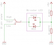
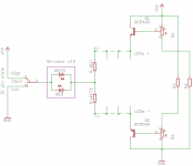
Now I have a fancy idea which I want to test (see attached). If IO pin is set "High" the white LED is on, if it is set "Low" the red LED is on, but if the pin is set to "Input" (high impedance) both LEDs are off. The current through the series resistors from +5V to GND should be no more than 1mA.
I hope I've got it right.
Attachments
Just about, yes 🙂
Lets throw some numbers in... LED volt drop say 2 volts for the red, say 3.5 volts for the white. Resistor value to give 1 ma in each is red = 3k and white = 1k5. R total = 4k5. Total current when no LED is lit = 1.1ma.
Lets throw some numbers in... LED volt drop say 2 volts for the red, say 3.5 volts for the white. Resistor value to give 1 ma in each is red = 3k and white = 1k5. R total = 4k5. Total current when no LED is lit = 1.1ma.
I just tested it on the breadboard with 5V supply and 5k potentiometer. It works great! 4k5 total resistance would be brighter but for now it works as the proof of concept. I am already sketching a PCB for the indicator🙂
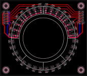
I've just sketched PCBs for the LED indicator (upper half done) and the MCP23017 driver for it (see attached). Two MCP23017's are necessary for one LED indicator.
I've included small (47~100 uF) local reservoir caps C1-C2 to the MCP23017 board since the power to the LED indicator goes through this board. Now I have a question if these caps can be moved to the LED indicator board (5~10 cm away)? The wire run from the PSU to the MCP23017 board can be up to 20 cm which seems to be a bit far. The MCP23017 has local ceramic decoupling capacitor C3 but would it be sufficient without the bulk capacitance or I am over-engineering here? Dropping the bulk capacitors would allow to shorten the MCP board by 5 mm which would help a lot to compactly place the boards on the front panel.
Could someone experienced advise on the subject?
Thanks,
Oleg
Attachments
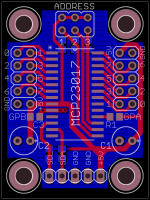
Looks good  I wouldn't like to say for sure what the decoupling requirements of the chip are. Maybe the data sheet specifies things better. How about retaining C2 and making it a small SMD type part, perhaps 10uf.
I wouldn't like to say for sure what the decoupling requirements of the chip are. Maybe the data sheet specifies things better. How about retaining C2 and making it a small SMD type part, perhaps 10uf.Thanks Mooly!
I think it is a good idea. I guess for the frequencies of I2C (400 kHz~1.5MHz) tantalum cap would be fine. I read the data sheet but probably overlooked this info. Will try to find if they specify anything regarding the local decopling of MCP23017.
I think it is a good idea. I guess for the frequencies of I2C (400 kHz~1.5MHz) tantalum cap would be fine. I read the data sheet but probably overlooked this info. Will try to find if they specify anything regarding the local decopling of MCP23017.
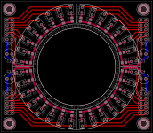
Just finished the LED indicator and MCP23017 PCBs (see attached). They will be mounted back to back. I will perform some more tests with LEDs on the breadboard before submitting the PCBs for manufacturing. May be adding LEDs supply voltage adjustment with a transistor to dim all the LEDs at ones would be a good idea but I am a bit unsure if the voltage drop on the transistor and MCP outs when fully open would not leave me with too low supply for the LEDs. Will decide after experimentation.
Attachments

Dimming the leds might not be so easy. If you at your diagram in post #27 then altering the supply will only alter the brightness of the top LED. The lower is driven from the chip at all times and so its brightness is constant.
Yeah, I realized that in first place. I thought of using two transistors initially: one in +5V supply leg and one in GND leg on the LED side. But this shortens the useful supply range to 4V or even less. My LEDs should probably be fine with that but some colors require ~3.2V to operate. I'll experiment with such a setup to make sure it works.
It really is the sort of thing you would have to experiment with. You could try and design a small dual tracking regulator. For this you would call the junction of the two resistors 'zero' or 'ground' and the output of the reg would be -/+2.5 from this point, and adjustable to lower voltages.
Yeah, I realized that in first place. I thought of using two transistors initially: one in +5V supply leg and one in GND leg on the LED side. But this shortens the useful supply range to 4V or even less. My LEDs should probably be fine with that but some colors require ~3.2V to operate. I'll experiment with such a setup to make sure it works.
You could also use a PWM generator in your micro to modulate the +5V for the LED supply, like through an LM317. All under software control! Add a photo sensor and you can automagically adjust brightness to ambient light level 😉
Jan
I thought of a similar possibility as well but I am not experienced enough to accomplish such mission. What worries me also is that L7805 reg which I use in the PSU can put out voltage in the range on 4.8~5.2VDC depending on part tolerance which may render LEDs to not glowing at all or brightly shining and both are undesirable (I noticed this for white LEDs). Selecting current limiting resistors based on particular L7805 part is not a good idea and it would really be good to have an on board supply adjustment possibility. I'll have to explore other possibilities which are simple enough that I can manage🙂 I've seen some dual rail (pos/neg) LDO regs with minimum external parts count which may be an option using the two resistor junction as virtual "0" as you suggest.
Hi Jan,
Posted reply to Mooly while you were writing...
Your idea has already been in my head as well using the dedicated LED driver which almost all have PWM control built in. But this makes the whole thing more complicated than I can manage. Since it is a one time project I would prefer to avoid complications which can require multiple prototyping stages before it actually works. At the moment it is simple enough for my skills that it would probably work from the first try. But the idea is fun enough to think a bit more before completely discarding🙂
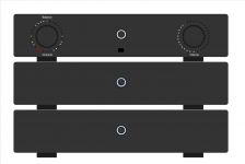
Well, the final goal is to have the design as attached. Volume controler/source selector and two power amps. I have it almost done except for the front panel of the line stage...
Regards,
Oleg
Posted reply to Mooly while you were writing...
Your idea has already been in my head as well using the dedicated LED driver which almost all have PWM control built in. But this makes the whole thing more complicated than I can manage. Since it is a one time project I would prefer to avoid complications which can require multiple prototyping stages before it actually works. At the moment it is simple enough for my skills that it would probably work from the first try. But the idea is fun enough to think a bit more before completely discarding🙂
Well, the final goal is to have the design as attached. Volume controler/source selector and two power amps. I have it almost done except for the front panel of the line stage...
Regards,
Oleg
Attachments
- Status
- Not open for further replies.
- Home
- Design & Build
- Construction Tips
- Driving LEDs by digital outs