The simple circuit would work but you might notice slight brightness changes as more or less LED's turn on/off. Ideally each should be a regulated supply that maintains output under load. You might find it a non issue though, particularly if using a high gain transistor (darlington... have we enough voltage overhead for that to work)
Could someone advise if the attached idea would work to adjust the LEDs supply voltage reliably? There will be up to 16 LEDs per transistor. Total collector current is around 30mA per transistor.
Thanks,
Oleg
I would include a base resistor to avoid possible damage should you accidentally turn the trimmer all the way up (or down).
Did you consider a single adjustment shifting the midpoint so that the you could regulate the brightness balance rather than the absolute value?
Jan
The varying brightness was my worry... Thanks for confirming it Mooly! May be it will not be so bad but I would prefer to avoid it. Regulators are a bit harder to use since the available voltage overhead is so small...
Its easy to try, just rig up one transistor and one LED and then dab a resistor across the output to pull the full load current when all LED's are on. You could see if high gain transistors minimised the problem.
Another idea, and I'm not sure what it would be like in practice, would be to have a switchable brightness control and use a chain of two or three diodes with each extra diode dropping another 0.6 volts or so from the total.
Another idea, and I'm not sure what it would be like in practice, would be to have a switchable brightness control and use a chain of two or three diodes with each extra diode dropping another 0.6 volts or so from the total.
Thanks Jan! I did not consider a single adjustment so far. How would I do it assuming fixed LOW/HIGH state voltages of the MCP23017 outs?
The idea with switchable diodes is a bit too extreme I guess. I played with the LEDs and 0.6V could already be too much for smooth adjustment, but thanks for the hint anyways.
OK, I guess its something you are just going to have to try ideas out on and see what works best.
I think I found my solution: I can use TPS73601 adjustable regs with extremely low dropout (75~200mV at 400mA max output) to set precisely the desired voltage for MCP23017 supply and for the LEDs. MCP23017 has 0.6V output LOW state and VDD-0.7V output HIGH state (and supply range of 1.8~5.5V) which gives me enough headroom to set the brightness of LEDs as I wish assuming 4.8V~5.2V (L7805 regs tolerance range) before the TPS73601 regs. This would make an indicator totally immune to what supply voltage comes in as long as it is not too far from 5V.
That sounds a good solution, I hadn't realised the 23017 would work over such a wide supply voltage.
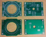
Just finished the updated PCB using the TPS73601 regs. Initially I wanted to have separate regs for the MCP23017 and for the LEDs side to independently control white and red LEDs but this could make the entire project even more expensive. So I stopped at only one reg per upper/lower deck. Now I can test and design for a fixed voltage after regs of let say 4.3V and still have enough adjustment range up and down to fine tune the brightness.
Attachments

Finally got the time to post an update.
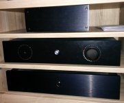
I've made the boards and assembled one indicator (see attached). It all works almost as intended and I really like it. But I have a little problem. As you might noticed some of the white LEDs have slightly lower brightness and if I turn the overall brightness a bit more down, some of them dim too much and are nearly off while others are glowing as I want them. So more work is needed to fine tune the indicator. There are two options that I see: I should either buy more LEDs and select them by brightness or mess around with individual current limiting resistors. And I don't like either of the solutions🙁 The LEDs are bi-color (white/red and yellow/red) 2mm type and cost around 1 Euro each on ebay (I have 32 of them in one indicator) which makes buying more LEDs not so attractive. Adjusting 64 resistors individually is also not so much fun...
The difference in brightness between the white and the yellow LEDs is expected and is easy to tune, which I'll do later.
So if someone knows a good source of 2mm bi-color LEDs which are not so expensive I would appreciate if you can give me a pointer.
Regards,
Oleg
Attachments

LED brightness vary much for different bins. You can try Cree, Osram, Nichia or other known brands . so you will not have to bother with adjusting resistors for each LED.
Their LEDs are reliable in brightness with their datasheets.
Their LEDs are reliable in brightness with their datasheets.
Looking really good 
I've never heard of white/red bi-colour LED's tbh so wouldn't know what to suggest for those (manufacturers).
I've never heard of white/red bi-colour LED's tbh so wouldn't know what to suggest for those (manufacturers).
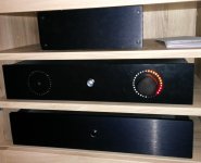
Yeah, I only found two guys on ebay who sell those, and I haven't seen anything similar on any of the big online electronics stores, e.g. mouser, digikey etc... But I really like the idea of leading red dot on my indicator🙂 It makes it more difficult to control but it looks really cool! The flash from my smartphone camera overexposed the front panel. In reality the LEDs are not so visible when off. The front panel itself is made of black PVC and is just for testing. Later I'll order the predrilled anodized aluminum panel from modushop to match my amp.
- Status
- Not open for further replies.
- Home
- Design & Build
- Construction Tips
- Driving LEDs by digital outs