Here are the three configurations at hard output clipping:
1.At 500Hz the driver current is rather not hitting the 0ma
2.At 20KHz the driver current is getting 0 and almost flat at the bottom with 10ma idle current
3.At 20KHz the driver current is still going to 0ma but for shorter duration with 35ma idle current.
Its quite surprising why its not happening at lower frequencies but rather happening at higher frequencies.
But at idle current 150ma where the driver is dissipating 12W continuous I see that the driver current is not hitting 0ma. Isnt it a high value? now the question is if that is done then there wont be any cross conduction?
It is no problem if the driver current hits zero. 150mA for the driver is a way too high. It can cause thermal problems. There is no 20kHz 0dB component in the common music, so I would say the maximum test frequency would be 10kHz.
Sajti
Use 1 pair of MJL3281/MJL1302 as driver. Crest using this solution in their PRO9200 amplifier. It must be strong enough to handle the driving current, and avoid the cross coduction.
Sajti
This is a good solution. Good driver SOA. Reasonably fast driver. Good driver dissipation to allow healthy driver bias of, say, 60 mA. Capable of driving high current into a big output stage, even under fault conditions.
May want more than 10 mA bias in pre-driver in a Triple to drive the somewhat larger Ccb of these driver transistors. 15023/4 pre-drivers not out of the question. Use of a Diamond Buffer Quad (DBQ, in my book) output stage also not out of the question for a big amp. The Bryston output stage is a Quad.
Cheers,
Bob
It is no problem if the driver current hits zero. 150mA for the driver is a way too high. It can cause thermal problems.
There is no 20kHz 0dB component in the common music, so I would say the maximum test frequency would be 10kHz.
Sajti
You never want the driver current to go to zero in a Locanthi Triple (or most other output stages) at any reasonable test frequency and power level (e.g., 20 kHz full power). That indicates that the driver losing control of the output transistor(s), which you never want.
150 mA in the driver is a bit on the high side, but not out of the question if the driver is a TO247 or TO264 mounted on the main heat sink.
Maximum frequency for testing of 10 kHz is way too low in general, whether music has 20 kHz 0 dB levels or not. If your amplifier cannot handle full power 20 kHz into a 4-ohm load, you may want to consider improving the design.
If you run your amplifier at near full power into a load, and increase the frequency from 1 kHz to 20 kHz, and see the current consumption increase substantially, that can be an indication of cross-conduction.
You always want good design margin. This usually translates to better reliability.
Cheers,
Bob
Thanks for the good information. I found that Crest Audio mixed the Locanthi solution with the resistor connected from driver emitter to output solution. I guess that this resistor can help somewhat once the driver current falls to zero.
For the 150mA driver bias means a risk for the thermal runaway, I think. 30-60mA looks fine, and I would use 1-2uF capacitor across the driver's emitter resistor. When I built PA amplifiers I used the popular 2SC4793/2Sa1837 as predriver, and for VAS, up to +/-80V PSU. It was fast, and reliable.
I used 50kHz low pass filter at the input to avoid high speed transients.
Sajti
I have never been a fan of using the "speed-up" capacitor across the driver emitter resistor, instead favoring enough driver bias current to make it unnecessary. Putting energy storage elements, like that capacitor, into potentially non-linear circuits, often has undesirable outcomes and unexpected effects.
Most of the time, virtually no signal current will be flowing through that capacitor in a Locanthi Triple. When there is a high rate of output current change (high output current slew rate), that is when output transistor turn-off is an issue, and when that capacitor may see signal current flowing through it if the driver bias current alone is not enough to sweep out the minority carriers from the base quickly enough. That current flowing in the speedup capacitor may be significant - tens of mA.
Think about the charge that will develop on that capacitor during the turn-off event and how big that capacitor may have to be to make much of a difference during that event. Then think about what happens to that charge and the effects it has after the turn-off event is over.
Cheers,
Bob
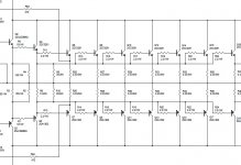
You need something like this.. look at ecler Pam 6100 schematic at elektrotanya..I was checking the other day about Meyer sound amplifiers Class AB/H and found that they are using some IRF140 or some Hexfet mosfet. I was quite interested to know that what if we use 15 pairs IRFp240/9240 instead of Bipolars like 6 pairs of MJL21194/93. One thing which attracts me is the no secondary breakdown in the mosfets i agree the fact about non linearity and other higher bias issues but in pro application like driving dual 18 inch subwoofers wouldnt mosfets are good enough. Now here is the question that what are points to consider if we use 15 pairs of IRFP240/ 9240 like a good TO264 package transistor would drive it? Consdier Im biasing each mosfet at about 20ma as its used more for the subwoofer application.
Attachments
Bob its understood about the problems with speedup capacitor. Hence a small value of 1uf film might be like a little helper than using a large value. Like you said we will look at the higher bias in the driver. I have a question that what if we use Mosfets to drive so how beneficial will that be?
I think the whole IPS needs to be slowed down instead of just using an RC filter at the input and since crest uses 3281s they are relatively high speed devices than the MJL21194s. The problem may not be that serious. Looking at Proline 3000 might be better call as they use MJL21194/93s all over the output stage over 15 pairs but I think that amp runs in more or less like in Class G than H.
2 stage with higher VAS current @ 15ma will work better with todays higher hfe transistors. 2sc5200 type have beta of at least 50 at 5A 5 * 8 = 40A with 800 ma of driver current
mje15031 beta of 150 at 500ma leaves roughly 6ma VAS load for 40A.
under load of 15A peak 1.2ma is required and the bandwidth is higher.
mje15031 beta of 150 at 500ma leaves roughly 6ma VAS load for 40A.
under load of 15A peak 1.2ma is required and the bandwidth is higher.
Last edited:
Hi
There are some good ideas here about building very high-power amps -"super amps", really. Most super amps are bridges and use 80-100V rails with output power ratings of 1kW+. For full-bandwidth designs the aim is to never have the amp clip, so high rails combined with bridge-drive to the speaker and the use of lots of output devices is the norm.
1kWrms into 8R is 126V peak at 16A. Obviously single-ended drive with 100V rails is not going to cut it. If the load is 4R, there is a chance but also a risk of clipping (89Vpk at 23A).
These days you can improve efficiency using class-G and three or more supply tiers. This greatly improves heat dissipation and THD does not have to be miserable, although if you look at the usual PA offerings built along this structure, it seems like a poor way to go. However...
The OE said this is to drive a subwoofer, so we only need response up to 160Hz or so. This opens the door to a lot of tried and tested techniques that are low- to medium-fi but completely ample for sub duties. Crown's DC300 comes to mind, using a technique of idling the outputs at zero, driven by large drivers (same type as outputs) that have low-value resistors in their emitter tied to the load. The outputs come to life at a certain power point and share the load. Rod Elliot has a project like this too.
You can take the zero-bias output stage into class-G land and reduce dissipation at high output without detriment. The front-end for any of this does not have to be fancy, and the ubiquitous Lin frontend will suffice.
A major point that has not been mentioned is the fact that every system with a single sub is flawed. bass is directional from the point of view of the listener, so there should really be a left and right sub fed with separate signal information. THX's bastardisation of their own numbering system calling a point-2 system point-2 is misleading. Their approach simply adds a second sub in parallel with the first and both have the same mixed bass signal. Having two physical subs that can be separated in space does help break up potential standing waves in the room, but it otherwise does nothing for the intelligibility of the sound.
In any event, having more than one sub however it is driven signal-wise, allows for each sub to have a smaller amplifier of simpler mechanical design and lower cost.
In my experience, bass "slam" does not come from sheer loudness; rather, it is the result of proper time alignment of the harmonics, which means you can experience it with decent headphones, such as Stax ESLs at low SPL.
Nothing wrong with using the higher-speed 3281's over the 21193/4 as long as you have enough SOA. Note that Crest also wisely uses a TO264 3281 as the driver as well.
Cheers,
Bob
I use Sanken 2SC6145/2SA2223, which are fast, and have higher SOA, comparing to the 3281/1302 family...
Sajti
I think the whole IPS needs to be slowed down instead of just using an RC filter at the input and since crest uses 3281s they are relatively high speed devices than the MJL21194s.
Input RC is enough, as it is not let the high speed step signals into the amplifier. They are using same driver with 21193/94 in the PRO9200, even the output is common emitter, which is more critical, i guess.
Sajti
Hi rhythmsandy,
Well. you're fixed on the woofer and enclosure. There is very little we can contribute and you would be much further ahead buying a class D amplifier. Plug and play. Failing that, just copy the amplifier you like. To design one here is simply reinventing the wheel. A pointless exercise.
-Chris
Well. you're fixed on the woofer and enclosure. There is very little we can contribute and you would be much further ahead buying a class D amplifier. Plug and play. Failing that, just copy the amplifier you like. To design one here is simply reinventing the wheel. A pointless exercise.
-Chris
- Status
- This old topic is closed. If you want to reopen this topic, contact a moderator using the "Report Post" button.
- Home
- Amplifiers
- Solid State
- Driving 8 pairs of MJL21194/93