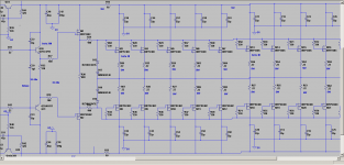
Bob I agree whatever you are saying what I mean to say is that If BJT is used then we will anyway have Beta droop. If mosfets are used then they dont have beta droop or secondary breakdown. Now can you please look at the sch attached will that be a right one to drive a 500W RMS sub? at +/-70V or so.
Now why Im looking towards mosfets in specific reason is at especially lowest note produced the cone grip will not suffer from beta droop of BJTs I think if we conservatively take like designing as per the SOA like under the DC line I think its more safer and yet delivers sustained current into the load when demanded at super low frequencies. Now can you please tell me is that circuit ok to drive the OPS or do I need to make any changes? Or do I need to stick to 5 pairs of MJL21194 93s driven with a 2sc5949.
Now why Im looking towards mosfets in specific reason is at especially lowest note produced the cone grip will not suffer from beta droop of BJTs I think if we conservatively take like designing as per the SOA like under the DC line I think its more safer and yet delivers sustained current into the load when demanded at super low frequencies. Now can you please tell me is that circuit ok to drive the OPS or do I need to make any changes? Or do I need to stick to 5 pairs of MJL21194 93s driven with a 2sc5949.
Attachments
Last edited:
For your subwoofer application I would suggest using BJT MJL21194/3 devices. This application does not justify or profit from the use of MOSFETs. Also, using MOSFETs for both drivers and outputs is asking for a lot of trouble because of the variances of threshold voltages from device to device. For a subwoofer, you just need a robust amplifier that can deliver a lot of current. The amplifier does not have to be super fast, although making it way more fast than enough is not difficult.
With a 70V rail and 3.5 ohm voice coil, your current peaks could be on the order of 20A or a bit more. That would be about 4A peak for each of 5 pairs. If all of the output devices have beta of 40, 500 mA will be needed to drive the output stage to 20A peak.
To be on the safe side, use TO-264 driver devices like MJL3281/1302, and robust pre-drivers like the MJE15032/3. This arrangement should provide plenty of safe area for the drivers and pre-drivers, even under fault conditions.
With combined minimum beta of this Triple of about 100,000, the sourcing of a peak output current of 20A will require well less than 1 mA. This will definitely not over-tax a single-ended VAS operating at 10 mA. If one is concerned about driving the higher Ccb of the 15032/3 devices, or desires more margin, the VAS can be run at 20 mA as long as decent heat sinking is used for the VAS to dissipate the 2.8W of its dissipation.
Bear in mind that we are not talking about high slew rates being needed here. Similarly, ULGF of between 250 kHz and 500 kHz is planty for this application.
I would argue that any properly-designed amplifier with a high current capability (e.g., 20A) and a damping factor of greater than 100 (extremely easily obtained at low frequencies) will have plenty of "grip" on the loudspeaker in this application. With plenty of SOA in the output stage, overly aggressive protection circuits that trigger needlessly are not needed; rather, protection circuits that have higher protection thresholds can be used (one must always provide reliable short-circuit protection). If you think you need more SOA, it is not a big deal to use, say, 7 output pairs instead of 5.
Once again, don't bother with MOSFETs for this application and recognize that beta droop should not be a problem here. Often, if you are sufficiently generous in providing adequate total SOA, you will end up using enough output pairs to significantly mitigate the effects of beta droop
Cheers,
Bob
Thank you very much for the suggestions Bob. Im only concerned with the heat dissipation of the VAS output transistor which Im currently using 1381 / 3503 but on a To220 suited heatsink like in the pic attached. Now considering the wattage dissipation of 2.8W is I think alot for the 1381/3503 transistor Im thinking of using 2sc5171 for the VAS transistors simulated with 0.004% at 500Hz at +/-68V output. On the ltspice sim I have considerded the current in load being 20Amp on high level output so with beta of 40 of the ops transistors the required input from drivers being 0.5A hence using a 2sc5949 ( which is a large TO 264 and can easily deliver 1.5A at that voltage but if you are specific to use MJL3281/1302 then I will use them but just to know why I have to be using that MJL transistor as drivers instead of 2sc5949). Now with 0.5A from the driver and beta of the transistor being 40 so it demands about 12.5ma from the pre drivers. Now predriver 2SC4793 having a beta of 100 and idling current of about 7ma for the predrivers then it demands only 47 micro amps or using 2sc5171 with beta being 200 so the current demand is even lower hence on the driving capability front i believe any of those above transistor can deliver the required current. Now what is the advantage of going with MJE15032/3 beast as pre driver is it purely for the fault condition? Or is there any other sonic advantage?
Bob how much idle current to be in the pre drivers and drivers in the above case?
Bob how much idle current to be in the pre drivers and drivers in the above case?
What about when we use a class A driver stage to drive the ops then the quiescent current need not be higher? Consider that the idle current is about 10ma and in the simulation even at full load the drivers are not shutting off. Is that combination ok or even in that idle current has to be large. As calculated the driver output current for the rated load we need approx 500ma so how much should be the driver idle current in the following circuit?
Attachments
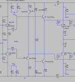
I say get rid of the current source/sink and go with a traditional 3EF. You can put a resistor between the emitters of the drivers and bias the drivers and pre drivers in class A. Putting a cap across the pre driver resistor won't do it.
Yes it is this but to know how it will affect output stage.yes read about it as minority carries stuck in the base and collectors.
As per the link I have given to you about Ostripper approach to the triple EF by using class a drivers and you have mentioned in which way it will stress it? I think the drivers are TO264 and the biasing transistor is also MJE15032 and 33 so cant they take up the stress? Im just curious that how will it stress can you explain?
The main disadvantage of a 3EF is it's increased saturation voltage, which reduces the leftovers of the supply rails significantly, hence causing bigger dissipation. So, what about cascaded Sziklai's, i.e. a NPN predriver, PNP driver and NPN outputs in the positive side, and their complementaries in the negative one? Any complaints about this?
Best regards!
Best regards!
The main disadvantage of a 3EF is it's increased saturation voltage, which reduces the leftovers of the supply rails significantly, hence causing bigger dissipation. So, what about cascaded Sziklai's, i.e. a NPN predriver, PNP driver and NPN outputs in the positive side, and their complementaries in the negative one? Any complaints about this?
Best regards!
crown pulse series? CROWN PULSE 2X1100 SCH Service Manual download, schematics, eeprom, repair info for electronics experts
The main disadvantage of a 3EF is it's increased saturation voltage, which reduces the leftovers of the supply rails significantly, hence causing bigger dissipation. So, what about cascaded Sziklai's, i.e. a NPN predriver, PNP driver and NPN outputs in the positive side, and their complementaries in the negative one? Any complaints about this?
Best regards!
The Diamond Buffer Triple (DBT) described in my book can help in this regard. Instead of preceding the output transistors with two EFs, the output transistors are preceded by a diamond buffer that does not incur the 2 Vbe drop.
A bigger benefit of this approach than getting the very last watt available from the power supply is the fact that, for a given output swing, it gives the VAS 2 Vbe more headroom. The pre-driver in the DBT shifts the voltage level up one Vbe rather than down 1 Vbe. The cost is the current source that is needed to source current from the rail to the emitter of the pre-driver.
The increased saturation drop of a 3EF Triple is not all bad in some regards. It keeps the base and emitter of the output transistor 1 Vbe further away from the rail when the amplifier clips. This can mean that less of the very dirty and ripple-filled main rail can get through to modulate the clipping level. The PSRR of the output stage goes to pot when the output transistors get into their quasi-saturation region.
Cheers,
Bob
The increased saturation drop of a 3EF Triple is not all bad in some regards. It keeps the base and emitter of the output transistor 1 Vbe further away from the rail when the amplifier clips. This can mean that less of the very dirty and ripple-filled main rail can get through to modulate the clipping level. The PSRR of the output stage goes to pot when the output transistors get into their quasi-saturation region.
Bob,
thanks. I'm scratching my head, though. How often do we want to listen to clipping amplifiers
 and notice that this clipping is modulated due to a dramatically decreased PSRR in this state?
Best regards!
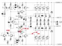
The final output of the Crown amp, swings 2*VBE less than the 2nd stage ("VAS" stage) swings.
That's not much of an improvement over a "Locanthi T" / "3EF" amplifier, whose final output swings 3*VBE less than the 2nd stage swings.
(VAS - 2*VBE) versus (VAS - 3*VBE) is insignificant when the supply rails are ±105V DC, to deliver 700 watts RMS per channel into an 8 ohm load, as the Crown does.
Oh and Crown seems not to have heeded Bob Cordell's advice to use one pair of output transistors per 75W RMS of max RMS output power. (Crown uses 4 pairs for 700W --> 175W RMS per pair.) I imagine Crown installs quite large fans with much MUCH greater airflow than Bob contemplated.
_
Attachments
- Status
- This old topic is closed. If you want to reopen this topic, contact a moderator using the "Report Post" button.
- Home
- Amplifiers
- Solid State
- Driving 8 pairs of MJL21194/93