Bob,
thanks. I'm scratching my head, though. How often do we want to listen to clipping amplifiersand notice that this clipping is modulated due to a dramatically decreased PSRR in this state?
Best regards!
The simple answer is that we NEVER want to listen to amplifiers that are clipping. I wish every amplifier had an accurate clip indicator LED. It would be an eye-opener for some. Amplifiers clip more often than we think, especially on well-recorded music with little compression and high crest factor, and especially when driving speakers of lower efficiency, sometimes on the order of 83 dB SPL one watt/one meter. I would especially like it if a clip indicator was available to reviewers when they review amplifiers.
Cheers,
Bob
The final output of the Crown amp, swings 2*VBE less than the 2nd stage ("VAS" stage) swings.
That's not much of an improvement over a "Locanthi T" / "3EF" amplifier, whose final output swings 3*VBE less than the 2nd stage swings.
(VAS - 2*VBE) versus (VAS - 3*VBE) is insignificant when the supply rails are ±105V DC, to deliver 700 watts RMS per channel into an 8 ohm load, as the Crown does.
Oh and Crown seems not to have heeded Bob Cordell's advice to use one pair of output transistors per 75W RMS of max RMS output power. (Crown uses 4 pairs for 700W --> 175W RMS per pair.) I imagine Crown installs quite large fans with much MUCH greater airflow than Bob contemplated.
_
The other day when I saw the inside of Crown amplifier I was shocked to see punny heatsinks I didnt understand the math involved in driving the transistor at edge. Why do they have to do it? Is it precise engineering or cost cutting factor or both? Even in QSC RMX i see 4 pairs of 2sc5200/1943 transistors driven at 78v rails. I dont know how they are calculating. Consider its super force air cooling but how does SOA is justified? I agree the OPS current will be limited but upto what extent?
The drivers need to be run quite hot to reduce cross-conduction. In a 3EF Locanthi triple, it is not unreasonable to run the drivers at 60 mA, so that 60 mA is available to pull minority carriers out of the output transistor bases. In fact, in a big amplifier with numerous output pairs, a TO-247 or TO-264 device can be used for the driver and even more bias can be run through the driver. These measures help with cross-conduction with lower or higher ft output devices.
By the way, by the time you get to serious cross-conduction, you have already suffered fairly high amounts of dynamic crossover distortion in the output stage.
In a simulation, one way to look for cross-conduction in a Locanthi Triple is to look at the waveform of the driver collector current. If and when the driver collector current goes to zero, the driver has lost control of the output transistor and you are pretty much in the cross-conduction region.
Cheers,
Bob
When It comes to driver conduction current I believe its more applicable in mid and high frequencies or will the distortion be much higher in lower frequencies also? for sub bass do we need to worry about the cross conduction?
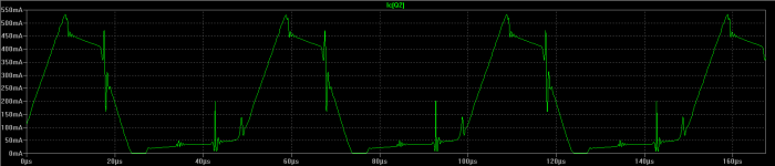
Please find the following waveform from the collector current where its not hitting zero. Is that correct way?
Please find the following waveform from the collector current where its not hitting zero. Is that correct way?
Attachments
Here is another pic with load being 1ohm both the above waveform and the one attached in the post is with class A driver stage. Its not touching zero. Both the above cases the driver is biased at 10ma. Hence I believe that will reduce the dissipation in the driver transistors yet doesnt turn off even at 1ohm load. Please correct me If Im wrong here.
Attachments
Were they getting burnt?The MJL21193/4 devices were tried a few times in Ostripper's Slewmaster EF3 design and they were catastrophically failing from cross conduction. We had to go to faster output devices to run reliably. If I recall correctly he recommended minimum 10MHz fT devices be used.
will try that sajti im getting few transistors of MJLs both 21194/ 3281/ 4281 and its compliments. Will surely try that but did crest use any technique for removing the cross conduction?
One thing which I have simulated is that at lower frequencies the driver current is not dipping and when I simulated at higher frequencies then to my surprise I saw serious dip in the driver idle current and even shockingly its not able to handle the dip even at 80ma of idle current. At 200ma of idle current the driver wasnt shutting off and it lower dip is about 10ma. Will send the pics of the driver idle current at 500Hz and 20KHz as my net is having slow connection.
One thing which I have simulated is that at lower frequencies the driver current is not dipping and when I simulated at higher frequencies then to my surprise I saw serious dip in the driver idle current and even shockingly its not able to handle the dip even at 80ma of idle current. At 200ma of idle current the driver wasnt shutting off and it lower dip is about 10ma. Will send the pics of the driver idle current at 500Hz and 20KHz as my net is having slow connection.
Hi Edmond,
Nice to see you posting!
Cheers,
Bob
Hi Bob,
I'm still posting, though less frequently and about a different subject,
please have a look at: DiAna, a software Distortion Analyzer
Cheers,
E.
will try that sajti im getting few transistors of MJLs both 21194/ 3281/ 4281 and its compliments. Will surely try that but did crest use any technique for removing the cross conduction?
They limit the slew rate at the input of the amp, to avoid high speed signal, and use high bias current in the driver, using 22-33ohm emitter resistor.
Sajti
You could easily blow up a lot of those big pro amplifiers square wave testing them at 100kHz. The assumption is that no user is ever going to do that with a speaker. Certainly not with a subwoofer.
Using proper slew rate limiting at the input can avoid this problem. Anyway 100kHz square wave is not typical in practice
Sajti
Limit the slew to fit the 4MHz Ft of the OPS?They limit the slew rate at the input of the amp, to avoid high speed signal, and use high bias current in the driver, using 22-33ohm emitter resistor.
Sajti
Limit the slew to fit the 4MHz Ft of the OPS?
No. Use low pass filter at the input for -say- 30-50kHz. This will limit speed.
Sajti
Here are the three configurations at hard output clipping:
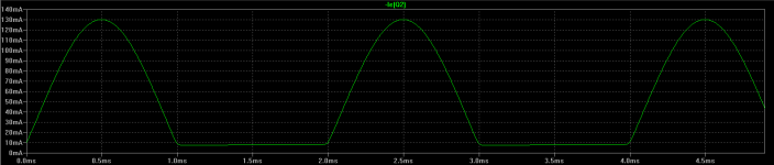
1.At 500Hz the driver current is rather not hitting the 0ma
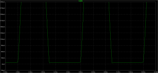
2.At 20KHz the driver current is getting 0 and almost flat at the bottom with 10ma idle current
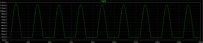
3.At 20KHz the driver current is still going to 0ma but for shorter duration with 35ma idle current.
Its quite surprising why its not happening at lower frequencies but rather happening at higher frequencies.
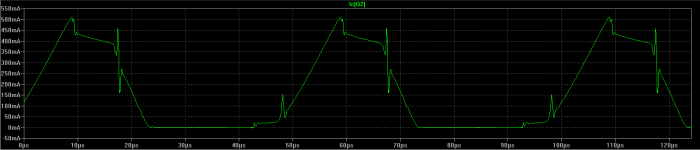
But at idle current 150ma where the driver is dissipating 12W continuous I see that the driver current is not hitting 0ma. Isnt it a high value? now the question is if that is done then there wont be any cross conduction?
1.At 500Hz the driver current is rather not hitting the 0ma
2.At 20KHz the driver current is getting 0 and almost flat at the bottom with 10ma idle current
3.At 20KHz the driver current is still going to 0ma but for shorter duration with 35ma idle current.
Its quite surprising why its not happening at lower frequencies but rather happening at higher frequencies.
But at idle current 150ma where the driver is dissipating 12W continuous I see that the driver current is not hitting 0ma. Isnt it a high value? now the question is if that is done then there wont be any cross conduction?
Attachments
Last edited:
Good old Nelson Pass has said in interviews that he often likes to use an input RFI filter with a corner frequency around 0.3 MHz. But his biggest amplifier is a meager 600 watts (and only a single channel!) so he might be playing in a completely different mud puddle than you guys.
- Status
- This old topic is closed. If you want to reopen this topic, contact a moderator using the "Report Post" button.
- Home
- Amplifiers
- Solid State
- Driving 8 pairs of MJL21194/93