I don't know what schematic you are referring to now (your first posting showed cathode bias) - but I would expect something like this for a MOSFET source follower:

These days I also use 1N4007 (or UF4007) from Source to Drain for ZVN0545A (newer MOSFETS often have this protection built-in but the ZVN0545A doesn't) and back-to-back zeners from Source to Gate. But you can also simply use a single zener like the above. You can directly couple it to the plate of the 6SL7. The coupling cap comes after the mosfet source follower.
I checked out the plate curves for the 6SL7 and estimated that with your B+, load and cathode resistor the plate will probably be around 200V. This means the resistor from source to ground should be around 75k - but you should check this yourself because sometimes plate voltages for 6SL7 can vary when using a resistive load...

This drawing is from the TSE-II from Tubelab shared in Post #16. It's a little more elaborate than the MOSFET Follies link you shared.

There's a negative voltage rail that I assume biases the MOSFET below 0v. Fancy. But necessary?
There's a negative voltage rail that I assume biases the MOSFET below 0v. Fancy. But necessary?
Hi, yes I see the whole schematic now. In this case, the coupling cap is in the correct position, and yes, you need a negative rail because if you don't your output tube won't be correctly biased.
Perhaps you need a stronger mosfet, with adequate cooling.
And instead of the source resister you could consider using a CCS (like a 10M90S, or some IXYS device). It’s best to make sure it works with a resistor first and then test with a CCS.
Regards, Gerrit
And instead of the source resister you could consider using a CCS (like a 10M90S, or some IXYS device). It’s best to make sure it works with a resistor first and then test with a CCS.
Regards, Gerrit
Hi gerrittube, the ZVN0545A device is chosen for it's low reverse transverse capacitance (Crss) value of 4pF. This is needed because of the very high output impedance of the 6SL7...
Yes, something like that. I would use something like 300 ohm grid stopper on the MOSFET and 1k ohm grid stopper on the 6B4G.
The cathode resistor on the 6SL7 seems a little high to me but I am sure it will work fine. You can certainly get away with sharing the b++ supply off the pre-amp tube.
edit: ok one thing.. you are using 6B4g right? The heater voltage is 6.3 volts.... so you are going to get some hum for sure if you don't come up with a DC heater circuit. It's DHT so you will hear that heater hum...
Something like this?
Does the MOSFET need its own node on the power supply or can it share the b++ supply with the preamp tube?
Yes, something like that. I would use something like 300 ohm grid stopper on the MOSFET and 1k ohm grid stopper on the 6B4G.
The cathode resistor on the 6SL7 seems a little high to me but I am sure it will work fine. You can certainly get away with sharing the b++ supply off the pre-amp tube.
edit: ok one thing.. you are using 6B4g right? The heater voltage is 6.3 volts.... so you are going to get some hum for sure if you don't come up with a DC heater circuit. It's DHT so you will hear that heater hum...
Yes, 6B4G output tubes. Amp started life as a 6v6 UL SE amp. Now I use the main PT to heat the driver tube and one output tube with a simple DC circuit, and I added another LV transformer for the 2nd tube.

The plate and cathode resistors are taken from the RCA Resistance Coupled Amplifier charts. Well, they show 2k1 and I had 2k and 2k2. But I might see how 1k8 does.
The plate and cathode resistors are taken from the RCA Resistance Coupled Amplifier charts. Well, they show 2k1 and I had 2k and 2k2. But I might see how 1k8 does.
ok I've looked at some parts. The ZVN0545A only comes in the small TO-92 package. Will this need additional heat sinking? it is operating at ~200v
the 15v Zener - 1W ok?
thanks for all the help
the 15v Zener - 1W ok?
thanks for all the help
It's about power dissipated. You need to multiply the drain - source voltage, then multiply by the current. It should be less than 0.5W to be safe. If higher, then just get a TO-220 MOSFET.Will this need additional heat sinking? it is operating at ~200v
Subtract, not multiply! The whole sentence is a mess. Hopefully you got the point 😅You need to multiply the drain - source voltage,
I like SF at about 10mA current, so TO92 is inadequate.
As you can see this sample, the SF FET dissipation is at about 1.5W, so TO220 version with appropriate heatsink necessary.

As you can see this sample, the SF FET dissipation is at about 1.5W, so TO220 version with appropriate heatsink necessary.
ok I've looked at some parts. The ZVN0545A only comes in the small TO-92 package. Will this need additional heat sinking? it is operating at ~200v
the 15v Zener - 1W ok?
thanks for all the help
No need for a heatsink if you keep it below 700mW. The 15v Zener can be 0.5W - I have been using some BZX55C15 but there are many others out there.
Last edited:
I like SF at about 10mA current, so TO92 is inadequate.
As you can see this sample, the SF FET dissipation is at about 1.5W, so TO220 version with appropriate heatsink necessary.
View attachment 1396696
Interesting. Never thought to use DN2540 for source follower before. I always used them for constant current source/sink duty. Crss looks low enough so why not?
For 6B4G I would still use DC on the heater though. This is not really that hard to do, plus I have some really nice boards that can do 6.3VAC -> 6.3VDC...
A bit of poking around on the Google led me to this post from @je245 documenting his Simple 45/2A3 Amp and it's quite similar to my amp.
@soulmerchant you are correct about the Kr on the 6SL7, he uses 1K.
So I got a couple things to try.
w
@soulmerchant you are correct about the Kr on the 6SL7, he uses 1K.
So I got a couple things to try.
w
If memory serves me right (I built this in the mid 90s), I started with 2.2k K resistor and lowered it to 1k because the 1kHz sine wave was more symmetrical at clipping and it sounded cleaner. After trying many other driver stages (SRPP, 56/76, 6J5, 5687, WE417A/5842, etc.), I reverted back to this hi-mu/lo-gm circuit for my SE45 amp.A bit of poking around on the Google led me to this post from @je245 documenting his Simple 45/2A3 Amp and it's quite similar to my amp.
@soulmerchant you are correct about the Kr on the 6SL7, he uses 1K.
Since you're chassis is limited to an octal triode with twin triodes, consider loading each half of a 6SN7 with a Hammond 156C plate choke, more details here. My main SE2A3 amp uses that same topology albeit with triode connected 6C6s + Intact Audio 200H nickel plate chokes and Tamura 7002 permalloy OPTs. I've also used and like the 2C22 and 6A6/6N7 in this circuit.
That or you can also add a dropping resistor in series between your choke and the 156C. Just do what you can to keep the current between 7-8 mA. I made a mistake of running 10 mA through the 156C, it sounded bad and the square wave @ 100 Hz collapsed = saturated core!As I already have a 2H Choke dropping the b+ where your circuit has the 6K8 resistor, I can only adjust Kr to ensure the Plate Choke doesn't see more than 8mA...
Over the decades I've collected around 90- 45 triodes, 60+ 2A3 triodes and at least 20+ 6B4G triodes. Some of my own findings, having tested every single tube in detail, follows:
- The 2A3 and 6B4G perform best with 3.5K Load. Better power and lower distortion. As you're using the Hashimoto OPT, I suggest using it with the full 3.5K primary.
- Also note that the Hashimoto OPTs will invert the output, i.e., the signal at the grid of the 6B4G and the standard output wiring on the secondary will be in-phase. Using a single driver will result in the output being out of phase.
- I designed a 2-stage input/driver many years ago using the Hashimoto iron. It requires about 250mv of input for full output. Using this, you don't really need a preamp, you can simply use an input selector and volume control for the equivalent of an integrated amp (if making a stereo build).
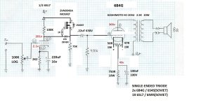
Attached is the 2A3 SET schematic. You can easily replace the 2A3 with a 6B4G and just implement a DC filament for the 6B4G. The original prototype for this circuit was done with a 6B4G. The input/driver has a gain of ~ 150V/V (about 43 dB) and can easily swing 150 volts peak-to-peak without any problems. Slew rate is high enough to be within 1dB at 50KHz (using Hashimoto H203S OPT).
Most of all, have fun regardless of how you decide to build.
- The 2A3 and 6B4G perform best with 3.5K Load. Better power and lower distortion. As you're using the Hashimoto OPT, I suggest using it with the full 3.5K primary.
- Also note that the Hashimoto OPTs will invert the output, i.e., the signal at the grid of the 6B4G and the standard output wiring on the secondary will be in-phase. Using a single driver will result in the output being out of phase.
- I designed a 2-stage input/driver many years ago using the Hashimoto iron. It requires about 250mv of input for full output. Using this, you don't really need a preamp, you can simply use an input selector and volume control for the equivalent of an integrated amp (if making a stereo build).
Attached is the 2A3 SET schematic. You can easily replace the 2A3 with a 6B4G and just implement a DC filament for the 6B4G. The original prototype for this circuit was done with a 6B4G. The input/driver has a gain of ~ 150V/V (about 43 dB) and can easily swing 150 volts peak-to-peak without any problems. Slew rate is high enough to be within 1dB at 50KHz (using Hashimoto H203S OPT).
Most of all, have fun regardless of how you decide to build.
Attachments
- Home
- Amplifiers
- Tubes / Valves
- Driving 6B4G with half a 6SN7 - SET amp