You need feedback to deal with distortion and damping. It's unlikely that the Hammond OPT will support 13dB of feedback, so you'll need to be sure that the loop doesn't include the OPT.
150V on the plate of the EL34 is, IMO, not enough. When you drive the 810 grid really positively, you're going to get pretty close to that 150V with the EL34 cathode voltage (AC peaks). Even tying it to the +275 node would likely be very helpful.
150V on the plate of the EL34 is, IMO, not enough. When you drive the 810 grid really positively, you're going to get pretty close to that 150V with the EL34 cathode voltage (AC peaks). Even tying it to the +275 node would likely be very helpful.
Last edited:
Thanks for the amazingly fast response!
What do you mean by "unlikely that the Hammond OPT will support 13dB of feedback"? I did include it in the loop - from the 8 Ohm tap back to the cathode of the 12HG7.
The reason I have only 150V on the EL34 is that if I go higher the plate current quickly rises above the 8mA limit for the choke and the cathode voltage rises too high to bias the 810 grid. I agree that it seems low and I think that this is a source of non-linearity.
To decrease the EL34 current, you can use a small adjustable negative bias supply to apply some negative voltage to G1.
With 13dB of feedback around that Hammond OPT, I suspect you would end up with an oscillator. Performance limitations of (most) series feed transformers will put a serious limit on the amount of feedback you can use around it.
With 13dB of feedback around that Hammond OPT, I suspect you would end up with an oscillator. Performance limitations of (most) series feed transformers will put a serious limit on the amount of feedback you can use around it.
I realized my comment about the EL34 plate current was based on looking at the plate curves and not experimenting. I just connected the plate to the 275V rail and found I got 20.5V on the cathode - which is 7.5mA through the choke. It made a big difference. With -13dB GNFB I now see 0.7% THD at 1W, 1.4% at 10W, 1.8% at 20W 4.7% at 30W and 10% at 40W. Admittedly I have let the plate current of the 810 rise to 140mA so I'm exceeding the specs of the OPT. I can see that I may well want the 1642SE as you suggest! I think a higher plate current will really help me. I can deliver 300mA at 800V with my B+ supply if needed.
So far I'm not getting any oscillations with the OPT in my GNFB loop. Or at least I don't see any. Would they be too high frequency to see in normal testing?
So far I'm not getting any oscillations with the OPT in my GNFB loop. Or at least I don't see any. Would they be too high frequency to see in normal testing?
Actually - let me correct myself - that's the cathode current of the 810 I'm measuring. And I'm now seeing 20-30mA with 0V on the plate - which I assume is the grid current. So right now I'm not exceeding the 120mA limit of the OPT.
You are running simulations in SPICE?
The phase shift of the OT will be the undoing of the feedback loop that encompasses the output transformer.
The phase shift of the OT will be the undoing of the feedback loop that encompasses the output transformer.
No simulations. This is all real. Attached is my latest THD graph. I realized I was using the 16 Ohm tap of the OPT to see what difference a 10K load made. Here it is at 8 Ohm/5K.

So you have a resistive load?
With the amp unloaded, you may find oscillations with a scope. If you attach a real world speaker (especially an ESL), things can get a lot worse.
With the amp unloaded, you may find oscillations with a scope. If you attach a real world speaker (especially an ESL), things can get a lot worse.
If you're going to leave this as-is, you'd want to at least determine what your phase margin is. Still, I'd take the feedback off the plate of the 810 and cap couple it to the cathode of the first stage or use the Schade feedback arrangement to keep the OT out of the loop. It will also sound a little better IMO.
Michi's regulator tube drive is basically what you're doing. The triode strapped EL34 has the GM that those regulator tubes do, and you're using a cathode choke instead of the CCS.
I find that his feedback implementations aren't really to my taste, but his work is a very informative body to study for sure!
I find that his feedback implementations aren't really to my taste, but his work is a very informative body to study for sure!

Very interesting - thanks for posting these. The first circuit is the same approach as I am taking. The other two (the fourth is the same as the second) use two different approaches to getting the bias voltage right by either a negative rail for the cathode follower or a self-biased output tube. I'm curious how the results would differ. Maybe I need to try them out?
Richard
Richard
Yes indeed. I want to try the MOSFET CCS too. Lots of drivers to try out!Michi's regulator tube drive is basically what you're doing. The triode strapped EL34 has the GM that those regulator tubes do, and you're using a cathode choke instead of the CCS.
I find that his feedback implementations aren't really to my taste, but his work is a very informative body to study for sure!
Even with everything going on in the world I have managed to spend some time here and there working on this amp. To be honest it’s been nice to have a project I can pick up and drop as time allows.
I started with only self-biasing on the EL34 cathode follower. This resulted in a 20V grid bias on the 810 which in turn resulted in plate currents well over the 120mA that the 1628SEA is rated for. I thought that results would be better (more power, better linearity) at higher plate currents so I took the plunge and bought a 1642SE (75W, 300mA). I’ll report back on that later, but I did find the frequency response “notch” at HF that others have talked about.
I did get some good results with plate currents up to 230mA. I pushed the limits of the 810 by upping the plate dissipation to the ICAS rating of 175W (eg. 800V and 220mA). I also compared the 1642SE and 1628SEA and found that there was no advantage in terms of frequency response or distortion. I have been pushing the peak power output of the 1628SEA (30W rated) to 50W for a few seconds to take measurements. It performs quite well.
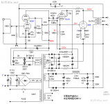
I did all this with positive bias on the EL34 grid using a voltage divider across the 150V screen supply. Then I decided to make a negative bias to see what would happen if I brought the plate current back down to the 120mA that the 1628SEA can handle. I was quite surprised at the results. With GNFB added I did run out of gain and decided to add a gain stage using a 5687. I’m attaching the schematic for my current setup.
Here’s a quick summary (I’m also attaching a graph):
810: 840V/120mA (100W Plate dissipation)
Pwr THD
1W 0.18%
10W 0.24%
20W 0.3%
30W 0.8%
40W 2.2%
48W 5%
Output impedance measures at around 1.5 Ohms.
I think there’s some instability in my amp at this point. If I try much more than the 9.6db of GNFB I get oscillations. I assume this is due to phase issues now that I have so many stages. I must admit that I haven’t paid much attention to any of that in the design yet. I expect that I’ll need a compensating capacitor in parallel with the GNFB resistor. I should probably do a proper analysis to look for poles etc. I did a bode diagram a year or so ago but forgot everything I knew! This can be another fun project as this experiment continues.
I will do a few more experiments with the 1642SE and publish the results. Then probably send it back since it looks like a $300 boat anchor for this project. That thing is gargantuan…
Feedback (none negative of course!) and comments most welcome. Thanks.


I started with only self-biasing on the EL34 cathode follower. This resulted in a 20V grid bias on the 810 which in turn resulted in plate currents well over the 120mA that the 1628SEA is rated for. I thought that results would be better (more power, better linearity) at higher plate currents so I took the plunge and bought a 1642SE (75W, 300mA). I’ll report back on that later, but I did find the frequency response “notch” at HF that others have talked about.
I did get some good results with plate currents up to 230mA. I pushed the limits of the 810 by upping the plate dissipation to the ICAS rating of 175W (eg. 800V and 220mA). I also compared the 1642SE and 1628SEA and found that there was no advantage in terms of frequency response or distortion. I have been pushing the peak power output of the 1628SEA (30W rated) to 50W for a few seconds to take measurements. It performs quite well.
I did all this with positive bias on the EL34 grid using a voltage divider across the 150V screen supply. Then I decided to make a negative bias to see what would happen if I brought the plate current back down to the 120mA that the 1628SEA can handle. I was quite surprised at the results. With GNFB added I did run out of gain and decided to add a gain stage using a 5687. I’m attaching the schematic for my current setup.
Here’s a quick summary (I’m also attaching a graph):
810: 840V/120mA (100W Plate dissipation)
Pwr THD
1W 0.18%
10W 0.24%
20W 0.3%
30W 0.8%
40W 2.2%
48W 5%
Output impedance measures at around 1.5 Ohms.
I think there’s some instability in my amp at this point. If I try much more than the 9.6db of GNFB I get oscillations. I assume this is due to phase issues now that I have so many stages. I must admit that I haven’t paid much attention to any of that in the design yet. I expect that I’ll need a compensating capacitor in parallel with the GNFB resistor. I should probably do a proper analysis to look for poles etc. I did a bode diagram a year or so ago but forgot everything I knew! This can be another fun project as this experiment continues.
I will do a few more experiments with the 1642SE and publish the results. Then probably send it back since it looks like a $300 boat anchor for this project. That thing is gargantuan…
Feedback (none negative of course!) and comments most welcome. Thanks.
Last edited:
The differences between the transformers will matter a lot more down low. Take measurements at 30Hz and you'll see differences.
Could you do a 1W frequency response plot on the big Hammond? I've wanted to do that myself but I haven't been motivated to buy one to measure.
Could you do a 1W frequency response plot on the big Hammond? I've wanted to do that myself but I haven't been motivated to buy one to measure.
Your wish is my command - especially with all the help you have provided!
First here are two graphs showing the 1W (0.06Vrms) sweeps for the 1628 and 1642:
1628SEA

1642SE

You can see the deep notch with the 1642SE starting just above 10 KHz. Other than that they look about the same (hard to see on the scaled graph).
First here are two graphs showing the 1W (0.06Vrms) sweeps for the 1628 and 1642:
1628SEA
1642SE
You can see the deep notch with the 1642SE starting just above 10 KHz. Other than that they look about the same (hard to see on the scaled graph).
Last edited:
Next the low frequency comparison. I didn't have the ability to test exactly 30Hz so here are two tests on each OPT at 50Hz and 20Hz. The 20Hz sweep starts at 0.1W since the THD was too high to start lower!
1628SEA @ 50Hz

1642SE @ 50Hz

1628SEA @ 20Hz

1642SE @ 20Hz

As you can see the 1628SEA holds its own at 50Hz and down at 20Hz the 1642SE starts to flex its 27lb muscles. I'm not sure it's worth keeping for that though. Thoughts?
1628SEA @ 50Hz
1642SE @ 50Hz
1628SEA @ 20Hz
1642SE @ 20Hz
As you can see the 1628SEA holds its own at 50Hz and down at 20Hz the 1642SE starts to flex its 27lb muscles. I'm not sure it's worth keeping for that though. Thoughts?
Last edited:
- Home
- Amplifiers
- Tubes / Valves
- Driver for 810 SE