You don't want a coupling cap sitting there trying to charge and discharge as the grid current wanders around.
Now that you've run into the issue of oscillations (which will be worse when you have a reactive load connected to the amp), you can do some research on alternate methods of applying feedback. IMO, you have two primary choices:
1. Use a feedback resistor from the 810 plate to the plate of the first stage (what I do).
2. Use a feedback resistor from the 810 plate to the cathode of the first stage (also valid).
At this stage in the game, you ought to also start factoring in output impedance. I wouldn't want an output impedance on the 8 ohm tap that's any higher than about 2.5 ohms, but to some degree this is also a personal choice.
The oscillation is a problem. Even with no GNFB it oscillates with no source attached. I wonder if I need to lower the value of the first grid leak resistor? Normally there would be a 100K pot there instead.
I'll try your two approaches to feedback. I'd like to calculate the value of the resistor. Do I use the same approach as for GNFB? I measured the open loop gain with the OPT as being 144. I assume the gain at the plate of the 810 would be 144*SQRT(5000/8) = 3,600. That would mean -15dB of NFB would require a 370K resistor. Does that seem right to you? I will also need to make sure the phase is right. I think it is. The 5687 and 12HG7 stages invert, then the EL34 CF does not, and the 810 does. So that means the 810 plate is inverted wrt the 5687 plate. That sounds right. I guess I'll find out if not. What would I do if it wasn't the correct phase?
I'll try your two approaches to feedback. I'd like to calculate the value of the resistor. Do I use the same approach as for GNFB? I measured the open loop gain with the OPT as being 144. I assume the gain at the plate of the 810 would be 144*SQRT(5000/8) = 3,600. That would mean -15dB of NFB would require a 370K resistor. Does that seem right to you? I will also need to make sure the phase is right. I think it is. The 5687 and 12HG7 stages invert, then the EL34 CF does not, and the 810 does. So that means the 810 plate is inverted wrt the 5687 plate. That sounds right. I guess I'll find out if not. What would I do if it wasn't the correct phase?
Also figured out that with a 390K resistor and a 580V voltage drop plate to plate that's 1.5mA and 0.9W. I should probably use a 2W resistor to be safe, especially if I use a lower value for more feedback. Even more current if I connect to the cathode.
For feedback, start with the damping factor you want, then work backwards. Your grid leak resistor has nothing to do with your oscillation.
A 580V drop across a resistor calls for a high voltage resistor.. 9W of dissipation calls for a 3W resistor. Vishay PR03 resistors will work for this.
A 580V drop across a resistor calls for a high voltage resistor.. 9W of dissipation calls for a 3W resistor. Vishay PR03 resistors will work for this.
I tried the plate to plate feedback. The phase was wrong - got positive feedback. I moved it to the plate of the 12HG7 and it definitely made a difference though not as good as the GNFB. I didn't use a high voltage resistor since I don't have any. Oscillation still there with source not present.
My output impedance is 1.5 Ohms measured (with GNFB) - so not too bad.
I want to resolve the oscillation problem since it shouldn't be there. Not sure where to look next.
My output impedance is 1.5 Ohms measured (with GNFB) - so not too bad.
I want to resolve the oscillation problem since it shouldn't be there. Not sure where to look next.
you should take 4 ohm output tap, green wire, not 16ohm and load 8 ohm, and 1642SE this its the way . i use for 304TL SE 1280V+B work wonderfullI looked at a 10K loadline too - the 1628SEA has a 16Ohm tap - if I connected an 8Ohm load to that I assume the 810 would see a 10K load? Would that compromise the sound quality too much?
Richard
The 1642 is about the worst SET amp output transformer on the market; this should not be recommended to anybody for anything, and Hammond should figure out how to fix the design.
it depend how you use thems,
my 304TL sound wonderfull with thems, low end spectacular, just use 4 ohm output
https://drive.google.com/drive/folders/1uljbdQQB9muXnGnpQloehz15iZemLoEp?usp=sharing
my 304TL sound wonderfull with thems, low end spectacular, just use 4 ohm output
https://drive.google.com/drive/folders/1uljbdQQB9muXnGnpQloehz15iZemLoEp?usp=sharing
If you drive them with a sub 600 ohm source, they work fine, otherwise the treble rolloff is extreme.
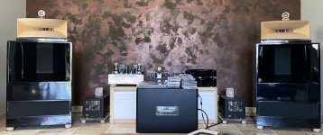
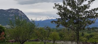
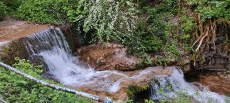
the auditorium have guest rooms in a manoir,beautyfull panorama and the finest withe wine
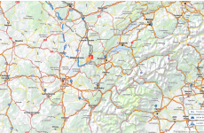
in France near Switzerland and Italy
i can offer you and your wife 3 days nights,
in France near Switzerland and Italy
i can offer you and your wife 3 days nights,
Attachments
yes but i lost the final dossier, starting point;Did you design the circuit? Did you measure its performance?
anyway the 304TL its home and i'm building two GM70 monoblock with 1638SEA@1KV 100mA
in few days i can check with 1642SE if you want, i have two spare new
Attachments
Last edited:
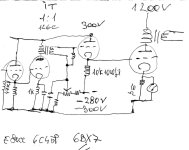
primitive schematics was developped , IT change to 5K 30mA, 6BX7 both triodes // voltages 1280V and xxx
the Savoia auditorium its open to visitors previus contact and rooms can be booked in advance
Audiowize if you wont to go let my now i book for you free
https://www.savoie-mont-blanc.com/chambres-dhotes/chateau-dapremont-6799921/
the Savoia auditorium its open to visitors previus contact and rooms can be booked in advance
Audiowize if you wont to go let my now i book for you free
https://www.savoie-mont-blanc.com/chambres-dhotes/chateau-dapremont-6799921/
- Home
- Amplifiers
- Tubes / Valves
- Driver for 810 SE