Yes, that is what it was all about really and this shows conclusively that its not. The TL074 was swinging 7.5 volts peak so that is what, 75 ma in total or 18 and a bit ma per opamp compared to 100ma (50ma per opamp) for the 5532.
True. NE5532 is the winner. I will use it in my upcomming projects.
Yes, that is what it was all about really and this shows conclusively that its not.
The TL074 was swinging 7.5 volts peak so that is what, 75 ma in total or 18
and a bit ma per opamp compared to 100ma (50ma per opamp) for the 5532.
Hi,
My rather subtle point is using two TL074's in your test
regimen driving 100R will not swing 15V peak, for double
the current, you will run into the swing limitations.
(i.e. one TL074 won't do 15V peak into 200R.)
So two TL074's won't do 150mA, so they won't "easily"
outdrive a single 5532, though they should surpass it,
but not by much really in the big scheme of things.
rgds, sreten.
Last edited:
That little test was quite insightful, thanks Mooly! It just about confirms what was already known.
TL08x/07x must have some pretty high internal output impedance, and coaxing them into giving anything near short-circuit current is not easy. I suppose that was a tradeoff for being quite fast for the time and current consumption. At 13 Vpp for a quad, we are looking at 16.25 mA into 400 ohms. Seriously wimpy things.
µPC324 as a quad relative of LM358 gives about 20 mA tops, in line with specs. Shame about the awful crossover distortion though.
Classic LM833 results look plausible - Samuel Groner ran into some current limiting at 7.75 Vrms (11 Vp) into 600 ohms, too. (From 4 Vp into 200 ohms you'd expect a maximum 12 Vp into 600, but it doesn't work out as well as that in practice.)
All the other parts are reasonably powerful at least, ranging from 40 to 50 mA per amp. The TI '5532 was looking to be a slightly better output driver than the original Signetics part in Samuel Groner's tests, too.
Parts that would still be interesting to see (but presumably were not floating around in the parts box) are NJM2068, as well as NJM4580 and NJM4556A.
Korean amp building enthusiast sijosae did some op-amp testing back in the day, with some interesting results. Since he was using a few different supply voltages, you get an idea of internal output impedance as well. An amp that just hard-limits at maximum current would give about the same output regardless of supply, while one limited by internal output impedance benefits from higher supplies. I suppose nobody will be particularly surprised to see an NJM072 in the latter camp, with particularly pitiful output at 9 V.
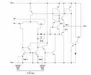
Its fun to do a reality check sometimes. The TL0 series does indeed have a high output impedance, just look at the equivalent circuit. The 'Excalibur' TLE2071/2/4 updated versions do considerably better as was confirmed in the test. Thing is though... I still rate the original TL0's for sonics while never being as happy with the later TLE series. Mind you, in typical line stages we are only looking at perhaps 1ma as a maximum kind of current delivery.
I think I do have some 2068's somewhere but they are scavenged SIL packages, haven't any of the others though.
Not seen that link before... thanks.
I think I do have some 2068's somewhere but they are scavenged SIL packages, haven't any of the others though.
Not seen that link before... thanks.
Attachments
Its fun to do a reality check sometimes. The TL0 series does indeed have a high output impedance, just look at the equivalent circuit. The 'Excalibur' TLE2071/2/4 updated versions do considerably better as was confirmed in the test. Thing is though... I still rate the original TL0's for sonics while never being as happy with the later TLE series. Mind you, in typical line stages we are only looking at perhaps 1ma as a maximum kind of current delivery.
I think I do have some 2068's somewhere but they are scavenged SIL packages, haven't any of the others though.
Not seen that link before... thanks.
Interesting those internal circuits.
Would the rather large open loop Zout not mean you can 'just' parallel a bunch of them, without any current share output resistors??
Jan
Would the rather large open loop Zout not mean you can 'just' parallel a bunch of them, without any current share output resistors??
Jan
I guess it would yes.
The thing is, it seems to be even higher than the resistor values would suggest. Those would sum up to 40 ohms for a quad, which you wouldn't think is that bad. Then again, in the 5532 it's only 15 ohm emitter resistors, plus whatever 1/gm is at output stage Iq.Its fun to do a reality check sometimes. The TL0 series does indeed have a high output impedance, just look at the equivalent circuit.
The '4558 still has that extra output series resistor as well, with similar results. '4560 up no longer do. TLE207x have some but obviously much smaller.
Hmm, now why would that be? They do measure at least about as good, and significantly better in a number of respects. All I can imagine is that being 3 times as fast, they are a fair bit more finicky when it comes to supply bypassing and layout. (Note how some audio amps like NJM2068, LM833, NE553x tend to keep unity gain frequency at sub-10 MHz while offering higher amounts of GBW further down.) Phase margin is specified at 57°, which is certainly adequate. TL07x phase margin is even supposed to be 45° only (in spite of the gain/phase graph suggesting huge PM in the order of 75°), and they are reputed to be quite allergic to capacitive loads at close to unity gain.The 'Excalibur' TLE2071/2/4 updated versions do considerably better as was confirmed in the test. Thing is though... I still rate the original TL0's for sonics while never being as happy with the later TLE series.
Last edited:
I used the TLE2072's in my preamp for a while to evaluate them (they replaced OPA2604's) and I was never happy with the result. I used them for several weeks and found that the 'enjoyment factor' was lacking. They were running on low impedance shunt stabilised rails and correctly decoupled. LM4562's have in many ways become my 'new reference' as I find them the most transparent of any.
which 833 gives the better driving capability?To satisfy my own curiosity on this I've just tested some opamps. The setup is as follows with each opamp in the package configured as a unity gain buffer. Both dual and quad devices tested all used 3.3 ohm 'balancing' resistors to sum the output. The setup was single rail, AC coupled and driving a 100 ohm load resistor. Level was increased until visible distortion appeared. Supply was 30 volts.
TL084, 13 volts pk/pk
An NEC upC324, 16 volts pk/pk (shame about the visible crossover distortion... Class XD needed 😉)
Texas NE5532, 20 volts pk/pk
LM4562, 18volts pk/pk
Ancient LM833, 8 volts pk/pk with hard +4 limit. Negative going OK to -8 volts.
Modern LM833P with quasi complementary stage 18 volts pk/pk. See following link,
http://www.diyaudio.com/forums/solid-state/274575-about-op-amps-use.html#post4361276
TLE2072, 16 volts pk/pk
OPA2134, 16 volts pk/pk
So there we have it 🙂
Edit... LM833 comparison attached.
which 833 gives the better driving capability?
This one. Post #54
http://www.diyaudio.com/forums/anal...opamp-compensation-technique.html#post4391591
You need to be very careful what you order.
But like I wrote elsewhere, output stage linearity for the TI "LM833" (// TI MC33078) is not expected to be very good. OK at low gains into loads well in the kOhms, otherwise a good candidate for some Class A biasing.
Its fun to do a reality check sometimes. The TL0 series does indeed have a high output impedance, just look at the equivalent circuit. The 'Excalibur' TLE2071/2/4 updated versions do considerably better as was confirmed in the test. Thing is though... I still rate the original TL0's for sonics while never being as happy with the later TLE series. Mind you, in typical line stages we are only looking at perhaps 1ma as a maximum kind of current delivery.
I tested the humble LM324N and it outputs much more power than the tl074, however soud quality is extremely disapointing.
Looks like TL074 is one of the less powerful opamps out there 🙂
Mooly if you have time to check , can you see with the osciloscope if there is some beneifts in biasing ne5532 or tl084 into class A (by adding a 3k resistor from the output to Ve-)?
like here :Tr-PS-2 & OpAmps and Tubes
Have a nice day 🙂
Mooly if you have time to check , can you see with the osciloscope if there is some beneifts in biasing ne5532 or tl084 into class A (by adding a 3k resistor from the output to Ve-)?
like here :Tr-PS-2 & OpAmps and Tubes
Have a nice day 🙂
In this application, this would be counterproductive I think. You're trying to wring 60+ mA out of each chip, and the class A bias can only be a few mA.
One thing that might reduce crossover distortion is to bias some of the chips, and to use several different bias points. That way they wouldn't all be crossing over at the same point and theoretically it could reduce distortion by several dB.
This design makes me wonder how well parallel buffered op amps would work as a power amplifier. Four buffers like the BUF634 or 49960 could deliver one watt into 8 ohms. Now parallel 32 of them
 and see how it works! I don't think you'd need 32 of them. Of course the money is silly but you could probably make a very low distortion amplifier.
I did parallel some 5532s on the breadboard and it worked well, but after 4 (2 chips) in parallel you've met the point of diminishing returns with regards to distortion and noise reduction. After that, all you gain is current capacity.
and the class A bias can only be a few mA.
If you shave off the opamp top and glue it to a large heatsink, it can be a lot higher. (Rjc <-> Rja)
Mooly if you have time to check , can you see with the osciloscope if there is some beneifts in biasing ne5532 or tl084 into class A (by adding a 3k resistor from the output to Ve-)?
The scope wouldn't reveal the change in stucture of the distortion when going into class A. You would need to analyse the residuals using suitable test gear.
If you shave off the opamp top and glue it to a large heatsink, it can be a lot higher. (Rjc <-> Rja)
You can clip a heatsink to a DIP-8 package. Old computers are full of these clip on heatsinks; they clip right to an anchor soldered onto the board.
But to heavily bias an op amp for class A operation in a power amplifier is very impractical. The amount of power available is small to begin with, and you're just scrubbing it off with heavy bias. Plus, you have to contend with DC offset.
Do you understand why using different bias points would mitigate crossover distortion? You could leave some of the chips unbiased and it plays right into this scheme. Think about it.
And finally, op amps operate in class A mode when buffered by devices like BUF634 and LME49600. Their input impedance is many megohms, and both devices can be biased for 15 mA quiescent current. Furthermore, these devices are rated for 250 mA continuous into a load. These buffers improve the performance of any op amp that is employed in almost any type of practical circuit.
The scope wouldn't reveal the change in stucture of the distortion when going into class A. You would need to analyse the residuals using suitable test gear.
Well, in case of crossover distortion it might me possible to see if it disapears. However I doubt that tl074 had any crossover distortion...
You can clip a heatsink to a DIP-8 package. Old computers are full of these clip on heatsinks; they clip right to an anchor soldered onto the board.
But to heavily bias an op amp for class A operation in a power amplifier is very impractical. The amount of power available is small to begin with, and you're just scrubbing it off with heavy bias. Plus, you have to contend with DC offset.
Do you understand why using different bias points would mitigate crossover distortion? You could leave some of the chips unbiased and it plays right into this scheme. Think about it.
And finally, op amps operate in class A mode when buffered by devices like BUF634 and LME49600. Their input impedance is many megohms, and both devices can be biased for 15 mA quiescent current. Furthermore, these devices are rated for 250 mA continuous into a load. These buffers improve the performance of any op amp that is employed in almost any type of practical circuit.
You pointed quite interesting ideas. However, if only some op amps are biased, the very small and hardly noticeable benefits will suffer from "dillution" when mixen with opamps that do not have the external biasing resistor.
I have to admit that I could not hear any difference when biasing TL074 into class A in my headphone amp. In spite of the tubecad article, I am not sure if biasing opamps can give real benefits, at least with tl074 or even with ne5532.
I apreciate Ideas given in you comment and I will try them 🙂 thanks!
And finally, op amps operate in class A mode when buffered by devices like BUF634 and LME49600. Their input impedance is many megohms, and both devices can be biased for 15 mA quiescent current. Furthermore, these devices are rated for 250 mA continuous into a load. These buffers improve the performance of any op amp that is employed in almost any type of practical circuit.
Agreed. I have several of both the BUF and LME to try this with. I believe a 5-10W amp using an octet of buffers should be possible.
Next on order is LT1210.... 1.2 amps continuous 🙂
- Home
- Amplifiers
- Chip Amps
- Doug Selfs NE5532 Power Amp. Thoughts anyone !