Cool. Kinda like a current-mirror loaded triode, only with constant current load on the supply rail.
Btw. I've done plenty current-mirrors PTP, no need for PCB unless you are afraid of crows nests in your build.
Btw. I've done plenty current-mirrors PTP, no need for PCB unless you are afraid of crows nests in your build.
Rod - I'm sure a few of us would be interested in a PCB if you get one together. Hopefully it would be adaptable for a few different DHTs including the 26, 4P1L etc., all the current faves. How does that sound?
Andy
Andy
Dear Rod,
Many thanks for the elaborate and detailed reply you have given to my question.
I am rather rusty these days, and will have to study the design at length before I can appreciate just how clever it is!
Paul
Many thanks for the elaborate and detailed reply you have given to my question.
I am rather rusty these days, and will have to study the design at length before I can appreciate just how clever it is!
Paul
Member
Joined 2009
Paid Member
Rod - I'm sure a few of us would be interested in a PCB if you get one together. Hopefully it would be adaptable for a few different DHTs including the 26, 4P1L etc., all the current faves. How does that sound?
Andy
Hi Andy - Yes, I think a board could be prepared that allows a Shunt-Cascode stage to be built and customised for any triode (DHT or IDHT), with one or two resistor changes only. The valve-base (tube socket) would probably best be mounted separately - so that any type of base can be used, and any mounting arrangement of the board in relation to the DHT.
Sounds good, Rod! Agree on separate sockets.
What driver do you use yourself with this circuit? Have you tried a few?
andy
What driver do you use yourself with this circuit? Have you tried a few?
andy
Sounds good, Rod! Agree on separate sockets.
What driver do you use yourself with this circuit? Have you tried a few?
andy
Hi Andy, I developed the circuit to work as a driver for 300B. I like plenty of gain in this application, so high-gm TV IF pentodes, triode-connected, work and sound best. I tried EF80, 6BW7, 6F23, 6F30, 30F5, and tuner triode PC86 - all sound good. Gain: 200 to 300 for a single stage. I tried the LP2 DHT in filament bias too, but they seemed a bit too microphonic, and the gain a bit low for 300B, and I did not experiment further with these.
The attached circuit, with the 2-stage MC preamp posted above, is my amplification from MC to OT - 3 stages only!
Attachments
Shunt current multiplier makes lots of tube choices.
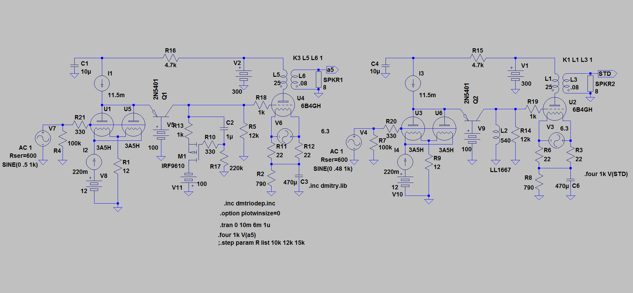
Not sure this is well thought out, but anyway an attempt at a true Lofting White version. Amp floats on output cathode and noise cancellation is made to input cathode. The ratio of input cathode resistor to string to output cathode should be about 1/u of the input tube.
I put the optional plate resistor in parallel with the current source that feeds the shunt transistor, so the option of blending in different load lines.
Sheldon
Attachments

Last edited:
Hi Sheldon, you may be on to something, and dc-coupling must be a real possibility with this circuit.
the flexibility to choose almost any triode, and run at any anode-current without altering the anode-voltage or the load resistor (hence gain) opens up opportunities out of the reach of most circuits.
I found that the base drive to the cascode has a strong influence on the sound, and using a divider buffered by darlington-connected MPSA92s + current-source pulldown is worth the trouble. I'm looking at a purpose-designed double-shunt-regulator to nail this voltage solid - while at the same time regulating the B+. With this scheme, the current source can be replaced with a resistor across the two fixed voltages. Thus, the self-noise of the whole stage will drop. (Not that it is bad....)
I really like the L/W approach. It works very well with a simple supply and no electro's in sight. So quiet, that I use this one as my headphone amp:
http://www.diyaudio.com/forums/tubes-valves/125488-loftin-white-801-amp.html#post1549712
The clever current multiplier in this thread opens up lots of possibilities. That, with current sources for filaments, keeps the sand confined to current management, and leaves the voltage amplification exclusively for the tubes.
Sheldon
Last edited:
[...]The clever current multiplier in this thread opens up lots of possibilities. That, with current sources for filaments, keeps the sand confined to current management, and leaves the voltage amplification exclusively for the tubes.
Sheldon
Yes, I've always felt this way, but I have problems understanding what's going on with the circuits discussed here... More study needed.
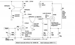
Meanwhile what is the thing in your circuit diagram that looks a bit like a diode in a circle?
thing in your circuit diagram that looks a bit like a diode in a circle?
A current source.

Member
Joined 2009
Paid Member
Now we're cooking, Sheldon already convinced me a while back on the Darius Loftin-White but marrying it with the Taylor shunt makes it all come together. I'll be using a 6C4C in place of the 2A3 and so I'd like to see the "Rod Coleman gyrator-CCS heater supply" included here too. I've looked at the base schematic for Rods heater supply (the public version) and I think one pcb could fit all this together into a nice package.
Last edited:
Hey Sheldon,
Have you considered the burnt away power in the cathode resistorst? It will be manageble though. By adding the anoderesistor I also suppose you worsen ripple figures?
If you go back and check the DC-design I did(the left one) it can be made with anything from 0 ohm resistors and up to cathode bias. If you go for normal cathode bias with 0V on the grid you have no current through the cascode load-resistor and can use any value you decide. It only takes the gyrator and a negative voltage of maybe 100V.
Take another look and you could maybe marry them to each other😉.
Last edited:
Member
Joined 2009
Paid Member
keeps the sand confined to current management, and leaves the voltage amplification exclusively for the tubes.
Sheldon
I like this philosophy, but is that how this design works ?
Since "active devices (tubes, transistors) modulate their current based on a control voltage input", voltage amplification occurs only if there is a high impedance load for the modulated current to flow through.
Cascode is a contraction of "cascade to anode". There are two stages here, the input tube feeding the BJT. The input tube works into a low impedance - the emitter of the BJT. Therefore, it generates very little voltage gain. The current flow through the tube is modulated by the input signal, but the voltage at the anode varies only slightly - in fact it varies just enough to ensure that the modulation of current through the BJT matches the current modulation by the tube.
The voltage gain is produced by the BJT device operating in common base configuration. The control voltage input to the BJT is the relatively small voltage signal at the anode of the tube feeding the emitter (since the base is at a fixed voltage) and the resulting modulation of current through the BJT produces a voltage drop across the resistor connected to its collector. This is a relatively high impedance and so produces a voltage gain at this collector. Doesn't this make the BJT the voltage gain stage ?
Could we look at this input stage as a compound device of 'tube + BJT'. Without the voltage variation with signal on the anode the result no longer behaves like a triode. I wonder if this is a case of a 'pentode wired triode' ?
More of the triode might shine through if the anode voltage was less firmly controlled by the BJT device by placing a resistor into the anode circuit (such as can be done in SS circuits - I did this in TGM5 for different reasons, which used an input cascode); it will be less linear.
Last edited:
- Home
- Amplifiers
- Tubes / Valves
- does the 3A5 have the stones to drive a 2A3?