That's why I scour hamfests and bargain suppliers for cheap (under $1) tubes to experiment on. I have lots of sweep tubes like the 25DN6's that I got for 50 cents each that I don't mind blowing up. So far, I think that I have killed two of them and I have about 80 more.
Post #20 here for pictures.
https://www.diyaudio.com/community/...-engineers-amplifier.406631/page-2#post-75427
Post #20 here for pictures.
https://www.diyaudio.com/community/...-engineers-amplifier.406631/page-2#post-75427
I note that the original Williamson had the output stage common cathode connected through a fixed 150R, then a variable 100R, then effectively a 75R to ground, which allows simple partial bypassing at 150R below the cathodes - which is essentially how Kiebert 1954 showed his partial decoupling for triode mode application in his Fig.12.
I recently had an 807 pentode mode Williamson on the bench (as per part of Kiebert 1954 discussion). REW makes it very easy to run SMPTE IM sweeps, and I noted a noticeable reduction in IM when 'regulating' the screen voltage, but didn't formalise the measurements. The existing amp used 2x 150V gas regulators in shunt mode for the 300V screen, and a noticeable improvement occurred using Alex Pogossov's modification ( https://www.valveradio.net/radio/improved-high-performance-glow-discharge-voltage-regulator.html) to allow substantial 'on screen' capacitor decoupling as per Kiebert's Fig.6. I had that amp on the bench a few years back and had added full bypass on the coupled cathode to noticeably lower IM, and noted IM <1% out to about 15W.
I recently had an 807 pentode mode Williamson on the bench (as per part of Kiebert 1954 discussion). REW makes it very easy to run SMPTE IM sweeps, and I noted a noticeable reduction in IM when 'regulating' the screen voltage, but didn't formalise the measurements. The existing amp used 2x 150V gas regulators in shunt mode for the 300V screen, and a noticeable improvement occurred using Alex Pogossov's modification ( https://www.valveradio.net/radio/improved-high-performance-glow-discharge-voltage-regulator.html) to allow substantial 'on screen' capacitor decoupling as per Kiebert's Fig.6. I had that amp on the bench a few years back and had added full bypass on the coupled cathode to noticeably lower IM, and noted IM <1% out to about 15W.

Maybe I'm not very well informed, but where did Allen write this? (Unintentional pun)After setting up the amplifier a 177R resister was used (1.25K*0,14) as Allen Wright had indicated.
Morgan Jones writes about the equalizing resistor in the 4th edition of his "valve amplifiers" book, where the uses it in his Bulwer-Lytton amplifiers (based on the 6S4A triode) that power the Arpeggio speakers, shown here https://www.diyaudio.com/archive/ar...hly-modern-tube-phono-preamp-prev-thread.html
He comments that the equalizing only works for a constant load from the OPT, so he makes the impedance of the Arpeggio "flat" with a zobel network.
In the 2nd edition of "building valve amplifiers" he describes the test procedure to match the valves to actually reduce the 3rd order harmonics: requires DC and AC matching, resulting in a lot of work and 50% of valves discarded. He concludes that it did not pick up in commercial gear due to that: some NFB also reduces distortion and requires much less efforts.
Far as I can tell the discussion of that circuit begins a few clicks back on p 31 of threadMaybe I'm not very well informed, but where did Allen write this? (Unintentional pun)
Huaji Audio 6P14P (EL84) + 6N1P PP amp kit build #2
Hope to run more tests today, all I need is time like everyone else. 👍Now compare construction type between your sundry 1.25K and a Anton-perry wirewound at 1.25K, that is designed specifically for low to no insertion loss, (Mills MRA5) you will see and hear a performance difference.
As a discerning audiophile, all my resistor are from Louis Vuitton.
I had always thought a resister by definition was a losser device.Now compare construction type between your sundry 1.25K and a Anton-perry wirewound at 1.25K, that is designed specifically for low to no insertion loss, (Mills MRA5) you will see and hear a performance difference.
A low loss resister somehow defies Gravity. And whatever else is happening in this luna-verse. 😀
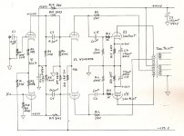
Here is the detail of the amp I used for this series of tests. Something I'd been curious about for a long time, bootstrapping the driverBy adding a resistor in the tail (roughly 1/gm) the current can be increased toward the edges so as to keep gm more constant.
for low mu triodes. In the Spring of 1998 I finally pushed ahead. The front end is a 2-stage diff amp with resistive tails to -150V.
Very few in audio use a negative potential other than for biasing of the output stage, Yet it was ubiquitous in the Op Amp buz, both SS & Toobz.
Some people object to the use of bootstrapping even tho it is used in McIntosh, Electrovoice & Circlotron amps.
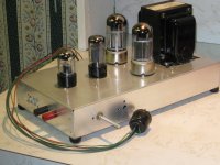
Crowhurst also use bootstrapping in his Twin Coupled amp. I've used in several times since in Crowhurst's Amp, this PP 6080 Amp & others.
Measuring & calculating the degree of positive FB we get 1.5 to 2 db. That is easily overcome by the external NFB path to whatever
degree the OPT will allow. I also used the resistive tails to -150V in all of these. Including a Class AB2 PP 6V6 amp.
At one time or another all of these amps I built have been here on DIY. So I will bore you with yet another set of slides.
Attachments
-
 6080 PP Amp Bootstrapped.jpg419 KB · Views: 150
 -
 6080 PP Bootstrpped Amp in July 1998 EW.jpg886.2 KB · Views: 149
 -
 Bootstrapped 6AS7 6080 Amplifier Schematic.jpg103.2 KB · Views: 145
 -
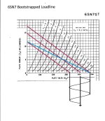 6SN7 Bootstrapped Loadline.jpg399.2 KB · Views: 130
 -
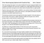 Driver Bootstrapping Explained With Graphical Help 2.jpg734.5 KB · Views: 116
 -
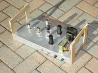
 6080 PPP Bootstrapped Amplifier.jpg362.2 KB · Views: 149
Bootstrapping for tubes can work very well.
Anybody that built various simple 3 transistor mid-power amplifiers that used a complementary NPN PNP emitter output, has probably used bootstrapping to increase the voltage swing of the input/driver transistor. Right?
Bootstrapping can work there too.
Anybody that built various simple 3 transistor mid-power amplifiers that used a complementary NPN PNP emitter output, has probably used bootstrapping to increase the voltage swing of the input/driver transistor. Right?
Bootstrapping can work there too.
Some might not recognize that as bootstrapping because of where it’s coming from. People used to seeing it used in a SS amp VAS get used to looking for a capacitor tied to the output (even in a class D driver for the mosfet), not a tap on a transformer. But anywhere with a low enough impedance point to drive from, and less than unity gain to the point being bootstrapped, the positive feedback is workable and provides an increase in available swing. The alternative here would be to run the driver stage off an extra high voltage supply, which may not be available. Or a pain in the *** to add. Those are the reasons bootstrapping gets used in SS work.
It could also be used the Yves Monmagnon Dissident Audio trick to set the positive feedback, or to limit the excursion of the voltage for the ccs suggested above.
Reference to this IMD scheme appeared recently in a thread posted by Never Get Old (NGO).
I've found the reference of the tests I've posted here:
https://www.diyaudio.com/community/...4-6n1p-pp-amp-kit-build-2.406195/post-7533720
It is here:
https://www.diyaudio.com/community/threads/el84-amp-baby-huey.72536/post-1498232
https://www.diyaudio.com/community/threads/el84-amp-baby-huey.72536/post-1498235
Concerning the notes I took about the 14%, I'm sure Allen posted in some other forums or maybe on his site, as here I only find me reporting it here:
https://www.diyaudio.com/community/threads/easy-diy-tube-amp.384618/page-6#post-6995533
Now thanks to smoking-amp we all know it was Kiebert who published in 1954 that 1/gm rule.
Bootstraps are where you find them (no matter what people decide to call them).
Example:
A cathode follower with 2 series cathode resistors; just return the grid resistor, Rg, to the junction of the 2 series cathode resistors. Bootstrapped!
At least 2 very early Tektronix high impedance probes . . . used this technique (with the tube all the way at the tip end of the probe).
Oh, for solid state fans, use a bipolar, JFET, or MOSFET.
History does repeat itself.
PP 6V6 Class AB2 Amp John L Stewart
This Amp looks like a good subject to use in trials of the Allen Wright Distortion reducing circuit. Trying at levels in Class A & AB with some grid current. Later this week we will see!
Circa 2001 I built this amplifier to satisfy some of my curiosities. None of these involved listening, but as always I did listen for a short while to be sure it was working properly. It was at a time when I was looking for experimental results from various circuit topologies. Not long after I got going on this project, another good looking contract appeared. So as usual, Money Talks & &hit Walks. The project made it to RAT but there was no article to get published in Glass Audio or AudioXpress.
This Amp was used briefly in another project published in AudioXpress Nov 2003. In that instance the project was a free running analogue switch with adjustable open time. An RF engineer would look at that one & recognize a Balanced Mixer.
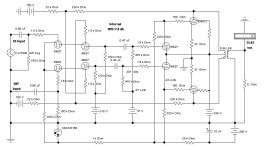
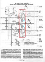
My amp curiosities included, what Class AB2 6V6s in PP would do while working from a limited PS as they do in a performers guitar amp & in comparison from a lab supply. Another point of interest was the use of an internal NFB connexion from the PP 6V6 plates back to the upper grids of a Differential Cascode frontend, the drain connected to a -150V volt.
The application of a similar internal NFB connexion I’d seen in one of Bill Perkins (Pearl) Amplifier Schematics, although in Bill’s case the NFB was from a tertiary winding on the OPT back to the screens of the driver tubes (PP 6AU6s). I had no OPT with tertiary windings & the G2 rg2 would load the NFB circuit. From other work I had found the looking in resistance of a common pentode voltage amplifier to be ~30K. If we dig enough in Terman Ed 4 we can find what Terman said on this subject.
It looked to me a way out & a more predictable result might be NFB to the upper triodes grids of a Cascode stage, that in order to avoid loading.
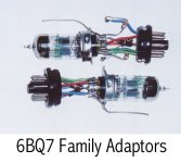
It might be a surprise to some I would use tubes of the BQ7 series as drivers in this amp. Earlier in one of the other experimental amps I’d built, I made adapters to use BQ7s to compare to the usual 6SL7/6SN7 2- Stage Diff Amp. The results were much better than I had expected. It seemed they would be suitable for this build.
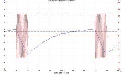
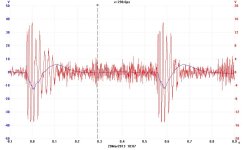
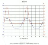
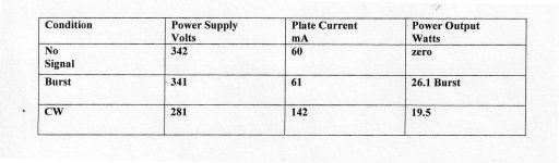
Most of the slides look to be self explaining. The 10 mS tone Bursts I think were at 10 watts. So we see a drop of 10V across the PS at the termination of C-L-C of 10 mF-10H-100mF from FWCT SS Source, Hammond 271X. The other is Peter Gabriel performing.
This Amp looks like a good subject to use in trials of the Allen Wright Distortion reducing circuit. Trying at levels in Class A & AB with some grid current. Later this week we will see!
Circa 2001 I built this amplifier to satisfy some of my curiosities. None of these involved listening, but as always I did listen for a short while to be sure it was working properly. It was at a time when I was looking for experimental results from various circuit topologies. Not long after I got going on this project, another good looking contract appeared. So as usual, Money Talks & &hit Walks. The project made it to RAT but there was no article to get published in Glass Audio or AudioXpress.
This Amp was used briefly in another project published in AudioXpress Nov 2003. In that instance the project was a free running analogue switch with adjustable open time. An RF engineer would look at that one & recognize a Balanced Mixer.
My amp curiosities included, what Class AB2 6V6s in PP would do while working from a limited PS as they do in a performers guitar amp & in comparison from a lab supply. Another point of interest was the use of an internal NFB connexion from the PP 6V6 plates back to the upper grids of a Differential Cascode frontend, the drain connected to a -150V volt.
The application of a similar internal NFB connexion I’d seen in one of Bill Perkins (Pearl) Amplifier Schematics, although in Bill’s case the NFB was from a tertiary winding on the OPT back to the screens of the driver tubes (PP 6AU6s). I had no OPT with tertiary windings & the G2 rg2 would load the NFB circuit. From other work I had found the looking in resistance of a common pentode voltage amplifier to be ~30K. If we dig enough in Terman Ed 4 we can find what Terman said on this subject.
It looked to me a way out & a more predictable result might be NFB to the upper triodes grids of a Cascode stage, that in order to avoid loading.
It might be a surprise to some I would use tubes of the BQ7 series as drivers in this amp. Earlier in one of the other experimental amps I’d built, I made adapters to use BQ7s to compare to the usual 6SL7/6SN7 2- Stage Diff Amp. The results were much better than I had expected. It seemed they would be suitable for this build.
Most of the slides look to be self explaining. The 10 mS tone Bursts I think were at 10 watts. So we see a drop of 10V across the PS at the termination of C-L-C of 10 mF-10H-100mF from FWCT SS Source, Hammond 271X. The other is Peter Gabriel performing.
Attachments
-
 027 Cascode Amp B.JPG718.5 KB · Views: 98
 -
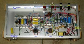 IMG_1383 Cascode Amp Bottom A 14W E Flash Labelled.jpg437.1 KB · Views: 106
 -
 Cascode Amp H.JPG54.8 KB · Views: 111
 -
 6BQ7 Family Adaptors.jpg41 KB · Views: 105
 -
 2013_03_23_002.jpg56.9 KB · Views: 86
 -
 2013_03_21_001 Peter Gabriel Salsbury Hill.jpg68.3 KB · Views: 80
 -
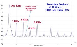 Distortion Products at 10 Watts B.jpg37.7 KB · Views: 87
 -
 Scope PP 6V6 Amp.jpg239.1 KB · Views: 79
 -
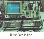 Burst Gate In Use.jpg60.1 KB · Views: 77
 -
 Scope PP 6V6 Amp.jpg239.1 KB · Views: 88
 -
 Pearl Page 9 PP 6AU6 Driver Stage 40C w Captions.jpg97.5 KB · Views: 100
- Home
- Amplifiers
- Tubes / Valves
- Does Allen Wright's Cathode Bias Resister Scheme for IMD Reduction Work? Yes? No? Maybe!!