Hi burntcoil.
I only know, what I hear when listening to different panel materials.
But most if not all tend to sound brighter from the exciter side.
It is obviously complicated by the noise from the exciter.
But in my understanding, it is to do with the skin effect.
Hi frequencies will spread out readily and freely along the primary surface from the coil.
But the high frequencies on the secondary surface have to travel through the panel material to reach the skin.
This does change,dampen, the sound from the front a little.
I prefer the sound from the front mainly because of the exciter problems.
This is why I was wondering if having the bolt though the panel will drive the front and back surfaces directly from the bolt on both surfaces?
Please feel free to say if you think this is wrong.
I would be interested in your thoughts.
Steve.
Hi Steve,
I think that’s the skin effect is a very credible explanation and deserves further thought and experimentation. I am not sure a bolt will work though, which is why I sketched out that pass through approach. It gives and option to adhere the tube and plate to the EPS all the way through the EPS thickness to make is a very stiff structure and transmit the impulse to both skins. With the bolt I also worry about the additional mass but I may be completely wrong on all the above. Only real world testing will determine what works as always. I would appreciate your views on all the above.
May I wish you an early Happy New Year as I often forget.
Burnt
Burntcoil.
I personally would not add any mass between the coil and EPS.
The bolt idea was for more rigid heavy panels.
Steve.
I personally would not add any mass between the coil and EPS.
The bolt idea was for more rigid heavy panels.
Steve.
Burntcoil.
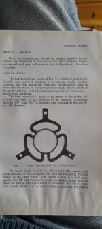
Thought you might be interested in this picture from G A Briggs book .
He has a section on spiders.
I have a spider in an old drive unit which is similar, which is best I do not know.
So there are other options maybe?
He regards the spider as a necessary evil.
Steve.
Thought you might be interested in this picture from G A Briggs book .
He has a section on spiders.
I have a spider in an old drive unit which is similar, which is best I do not know.
So there are other options maybe?
He regards the spider as a necessary evil.
Steve.
Attachments

I thought this patent should probably go here , if it is actually viable ?
https://patents.google.com/patent/US20220345825A1/en
Found by chdsl.
Steve.
https://patents.google.com/patent/US20220345825A1/en
Found by chdsl.
Steve.
Thank you Steve. I appreciate the thought and yes I am very happy to receive patents on motor systems. Having read this one I think its claims are dubious. You can achieve the same effects just by winding more wire on the former. It looks like another patent intended to stake a claim on a technology that is already well defined and in use. It happens all the time. Patents are legal devices used to seek and protect commercial advantage. They can and do contain useful technical data but, as in this case, they don't have to.I thought this patent should probably go here , if it is actually viable ?
https://patents.google.com/patent/US20220345825A1/en
Found by chdsl.
Steve.
Burnt
This is why I try not to read patents, they say everything, and at the same time, nothing.
Steve.
Steve.
I understand your frustration. To be valid a patent must describe how you can replicate the invention so there is often useful information in a 'real' patent. Unfortunately there are a lot of patents that exist that are designed to ring fence a technology with minute and often irrelevant modifications to the 'real' patent. These have little merit for us but do the job of protecting commercial interests.
Burntcoil.
I presume we are including NXT patents in this.
Although they do include exciter placements which is handy.
And there is some useful information buried in there if you can figure it out.
I think it was more about the software and tying people into contracts ?
That went well.
Steve.
I presume we are including NXT patents in this.
Although they do include exciter placements which is handy.
And there is some useful information buried in there if you can figure it out.
I think it was more about the software and tying people into contracts ?
That went well.
Steve.
The NXT patents were written by a combination of Farad Azima and Martin Collums, both well respected audio engineers and I personally find the signal to noise ratio in NXT patents to be high. Patents are a tough read and it takes time to develop the best approach to reading them. I had to read a LOT of patents in my business. I always go straight to the claims which, to form a valid patent, must contain an accurate description of the novel aspects of the design. Only after that will I read further. NXT were working on an earlier application from the Ministry of Defence after obtaining a Development licence from HMG, so the basis for NXT patents is an expansion of military R&D, usually pretty hardcore research. The patents I object to are the ones where someone elaborates on a known physical principle disguising that principle in lots of jargon. Written plainly the patent would be rejected as it would expose the claims were not novel
While I am waiting for components to arrive I have been looking at how Teragaki-Labo use exciters and there are a some aspects that are very interesting.
You can see from the image below that they use a lot, six is not exceptional. They also position them symmetrically with no attempt to find a 'hot spot' to excite modes.
They are also huge relative to the size of the panel similar in size to the magnet structure for a 100mm mid-bass or even a 165mm driver.
There is one more thing that, as far as I am aware, is unique to these speakers. They use a mix of 4ohm and 8ohm motors as the bandwidth varies according to impedance. There is no XO used, they rely on the difference in response due to the difference in impedance.
This last aspect I find intriguing.
Burnt
This is a better picture of what is going on.
https://www.monoandstereo.com/2015/02/teragaki-labo-sp2000-shiraki-speakers.html
The six exciter placements look very similar to what is shown on the other site.
I have seen this before but I don't seem to remember any measurements, but the recordings sound nice.
Steve.
https://www.monoandstereo.com/2015/02/teragaki-labo-sp2000-shiraki-speakers.html
The six exciter placements look very similar to what is shown on the other site.
I have seen this before but I don't seem to remember any measurements, but the recordings sound nice.
Steve.
Are the extentions at the back of the magnets to stear the flux ?
https://www.monoandstereo.com/2014/10/tengaki-labo-gemashita-terra-sp3000.html
Do they say that they mix the ohms for other reasons than having a standard ohm rating for their panels?
Steve.
https://www.monoandstereo.com/2014/10/tengaki-labo-gemashita-terra-sp3000.html
Do they say that they mix the ohms for other reasons than having a standard ohm rating for their panels?
Steve.
This is a nice sounding video, but I would expect this type of panel to excel at playing this type of music.
It was also interesting the photo of the extention to the coil, this would tie in well with the sort of exciter I was talking about, I must do a drawing to explain this ?
Steve
It was also interesting the photo of the extention to the coil, this would tie in well with the sort of exciter I was talking about, I must do a drawing to explain this ?
Steve
Hi Steve,
Yes I have seen those images and they are interesting. I have no idea what the extensions to the drivers are for and the Japanese website does not go into much detail on the motors. The details I could gleam were more about the need for a very robust frame, the original design used logs as a perimeter frame, and the use of 2mm thick balsa for the diaphragms which are hand made and varnished with special care taken with the varnish and the placing of the curved struts. The curvature is introduced to raise the resonant frequency of the panel. The motor array doesn't take any notice of modes or special positions as you say so although a DML, the evolved design is very different to what we are used to exploring.
Te design was evolved by trial and error from an initial design that had the massive log frame and a flat panel reinforced with ribs. The development was iterative recursive approach led by listening tests. Very interesting and it opens up the design space significantly. I am going way of topic so now will return to exciter designs. I have found a way to ditch the spider for Option 1 which I need to detail to get the components made so I am focussing on that.
Burnt
Hello BurntHi Steve,
Yes I have seen those images and they are interesting. I have no idea what the extensions to the drivers are for and the Japanese website does not go into much detail on the motors. The details I could gleam were more about the need for a very robust frame, the original design used logs as a perimeter frame, and the use of 2mm thick balsa for the diaphragms which are hand made and varnished with special care taken with the varnish and the placing of the curved struts. The curvature is introduced to raise the resonant frequency of the panel. The motor array doesn't take any notice of modes or special positions as you say so although a DML, the evolved design is very different to what we are used to exploring.
Te design was evolved by trial and error from an initial design that had the massive log frame and a flat panel reinforced with ribs. The development was iterative recursive approach led by listening tests. Very interesting and it opens up the design space significantly. I am going way of topic so now will return to exciter designs. I have found a way to ditch the spider for Option 1 which I need to detail to get the components made so I am focussing on that.
Burnt
By extension do you mean the white part between the voice coil and the membrane? I have always in mind to test a point driving...
The curvature gives stiffness in the direction across the grain. In a thesis about piano soundboard, it is explained that this increase of stiffness has a limit in frequency when the wavelength comes in the range of the distance between the ribs.
An other observation is about the opening of the engine between the spider and the magnet to avoid probably spider noise.
The voice coil seems very long too.
Hi Christian,
No the extension Steve is referring to looks like it might be an extension to the magnetic circuit which you can see on the left in this picture

What isn't obvious in this shot is that the extensions are something like 200mm deep and that is not including the circa 60mm thickness of the large wooden mount the motors pass through. This implies a very large magnet assembly and potentially a high B component. But equally clearly there is a large ferrite magnet visible from the front which is a bit more conventional. All very confusing. Its difficult to tell without a sectional view or a patent but I am not sure there are any patents for this design, I have not been able to find any
I agree that the white extension attached to the voice coil is probably a force concentrator and it also helps deal with the curved surface of the panel. The point drive is something I want to experiment with at some point and I am trying to develop a set of modular components that will allow me to experiment with a variety of motor structures and panel 'drivers' I will put links to these components up on the site for anyone to experiment with once I have settled on component designs that work well together.
On the panel design I also would anticipate that the ribs restrict the bandwidth and you will see in several other images a great deal of experimentation has taken place to establish best positions. However, its difficult to be sure because the only music I have heard played on them is also bandwidth limited. Teragaki-Labo used to sell a 10inch paper bass cone with the panels to handle the bass but there is mention that later on this was dropped and the response of the panels were extended.
The effect of the curve is intriguing and something I intend to experiment with in due course. As is the use of drivers with bandwidths tailored using just the voice coil impedance which is a novel approach.
Burnt
No the extension Steve is referring to looks like it might be an extension to the magnetic circuit which you can see on the left in this picture
What isn't obvious in this shot is that the extensions are something like 200mm deep and that is not including the circa 60mm thickness of the large wooden mount the motors pass through. This implies a very large magnet assembly and potentially a high B component. But equally clearly there is a large ferrite magnet visible from the front which is a bit more conventional. All very confusing. Its difficult to tell without a sectional view or a patent but I am not sure there are any patents for this design, I have not been able to find any
I agree that the white extension attached to the voice coil is probably a force concentrator and it also helps deal with the curved surface of the panel. The point drive is something I want to experiment with at some point and I am trying to develop a set of modular components that will allow me to experiment with a variety of motor structures and panel 'drivers' I will put links to these components up on the site for anyone to experiment with once I have settled on component designs that work well together.
On the panel design I also would anticipate that the ribs restrict the bandwidth and you will see in several other images a great deal of experimentation has taken place to establish best positions. However, its difficult to be sure because the only music I have heard played on them is also bandwidth limited. Teragaki-Labo used to sell a 10inch paper bass cone with the panels to handle the bass but there is mention that later on this was dropped and the response of the panels were extended.
The effect of the curve is intriguing and something I intend to experiment with in due course. As is the use of drivers with bandwidths tailored using just the voice coil impedance which is a novel approach.
Burnt
Last edited:
This video gives a clearer view of the unusual motor design at mark 4.31
N.B. I think the distortion evident at circa 9.20 onwards for a couple of minutes is due to the phones microphone overloading
Burnt
N.B. I think the distortion evident at circa 9.20 onwards for a couple of minutes is due to the phones microphone overloading
Burnt
- Home
- Loudspeakers
- Full Range
- DML Exciter Design