I must be using my multimeter incorrectly. I plugged the amp back in to take another measurement and both sides showed a positive 25.57. I pulled the probes out of multimeter sockets and reconnected them, and both sides were both negative again.
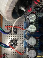
I'm measuring as indicated in the photo tutorial for the Aleph J, from the ground eruoblock to a V- slot on the negative side, and from a ground to a V+ on the positive side.
I'd think that if I really was switching polarity like that my capacitors would be leaking. But what do I really know?
I'm measuring as indicated in the photo tutorial for the Aleph J, from the ground eruoblock to a V- slot on the negative side, and from a ground to a V+ on the positive side.
I'd think that if I really was switching polarity like that my capacitors would be leaking. But what do I really know?
Attachments
I will. Even though it will almost certainly be humiliating. Back at it in the morning.
Thank you.
Thank you.
naw, you're learning.I will. Even though it will almost certainly be humiliating. Back at it in the morning.
Thank you.
I was lucky and my dad was an electronics technician in the Navy. The internet is helpful but slow compared to having someone look over your shoulder and explain things as you go.
If everything is correct, measuring the voltage across V+ to V- (red to black) should be on the order of 50VDC.
The rectifier wiring looks correct unless I'm missing something.
Or, just don‘t change the probe connected to ground, swap only the probe to the + / - like red probe + and black probe gnd, then red probe - and black probe gnd…

OK, got the multimeter problem solved, measurements on the PSU are good. However I have an actual issue now. I did the power up test on one of the amp boards using the dim bulb tester. At first the bulb behaved as it was supposed to, it went bright, then dimmed, but then faded out completely. Any idea what that means?
J
J
Although I can’t explain it, I can tell you that it is ok. If you want the bulb to keep glowing, use a smaller wattage on the bulb (if available, doh!)
(I‘m a noob too, with eventually some advance as I’ve already been there… some 2 years ago I started a thread about the dim-bulb‘s magic, with some infos and some riddles from the masters: https://www.diyaudio.com/community/threads/light-bulb-tester-just-how-does-it-work.365975/ )
(I‘m a noob too, with eventually some advance as I’ve already been there… some 2 years ago I started a thread about the dim-bulb‘s magic, with some infos and some riddles from the masters: https://www.diyaudio.com/community/threads/light-bulb-tester-just-how-does-it-work.365975/ )
Fascinating, left ear! Perhaps I shall push on with hope in that case, and see what the bias and offset adjustments tell me. Thank you very much.
J
J
As myleftear said. A dim or non-glowing bulb indicates no short in the amp. The circuit is effectively open (key being "effectively"). It may be allowing current to flow but the amp is doing it in a controlled manner. If there was a short in the amp, the tester + amp circuit would be allowing electrons to flow to ground uncontrolled, allowing the electrons to flow across the filament, lighting it up.
You can pull significant current in an incandescent lamp and see "no" glow. The light output falls off very much faster than the current. Depending what you are testing, this may be quite normal.went bright, then dimmed, but then faded out completely
I have a legitimate issue now. I'm not measuring any DC voltage at all across the 0.47 source resistors. I assumed I was using the multimeter incorrectly again, but even I can tell that the heatsinks aren't the least bit warm after several minutes of the unit being on. Both channels have the same problem despite the fact that the LEDs come on for both of them, which makes me think I installed a part incorrectly somewhere, put the zener diodes in backwards or something like that. Any idea where to start with troubleshooting?
J
J
The pots are simply installed. I haven’t touched them otherwise. They’re the 25-turn variety. I guess I assumed they wouldn’t have shipped turned all the way down (the bias pots in the ACA parts kits were pre-set somewhere in the middle). But why should I assume Digikey would send me the same thing?
I swear 6sX7, you really have a way of making me laugh at myself. I’ll take a wild guess and assume you turn the screws clockwise to increase bias?
I swear 6sX7, you really have a way of making me laugh at myself. I’ll take a wild guess and assume you turn the screws clockwise to increase bias?
Glad to hear that you have fun at life. Many times, we take ourselves way to seriously.
If I recall my F6es, factory setting of the pots resulted in no bias voltage. Also, with how my pots are soldered in, it is actually CCW. Drives me mad but that is how 6L6 soldered his in so I copied. I haven't tested to see what happens if the turnscrew placement is opposated.
It took a bit of turns and had to be patient and careful I didn't turn too many times too soon. It takes a bit to charge up the caps.
OK something’s happening here. Many many turns and the DC voltage jumped up to about 65mV pretty quickly, though now we seem to be stuck near there. In the last ten minutes it’s crept up to 68 then gone back down again despite about another 10 turns or so. Is this a normal thing? Because it seems like it’ll take a hundred turns to get to the recommended 500mV.
Might be time to hop over to the F6 build thread.
https://www.diyaudio.com/community/threads/f6-illustrated-build-guide.277850/page-223#post-7089972
In the meantime, what value of Zener did you use?
https://www.diyaudio.com/community/threads/f6-illustrated-build-guide.277850/page-223#post-7089972
In the meantime, what value of Zener did you use?
I used the 5.1 V Zeners the BOM called for. Funny you should ask that, my JFETs came with four Zeners with no explanation and no values indicated anywhere. I still have them, but since I have no real way to determine their value I'm not sure what I should do with them.
The parts values are weeeeee very tiny indicated on the part itself. I use my cell phone camera and/or a pair of high(ish) magnification lenses to read them.
As a side note, if you saw no values indicated, make sure you were consistent between Z1 and Z2 and between your "left" and "right" boards. The good news is that Zeners are relatively inexpensive and usually in stock. If you need to swap a few out, you're in good shape. I don't personally like desoldering and reusing them. They're cheap and cheerful parts that generally don't warrant recycling, IMHO vs. the potential for bad things happening if they're damaged while trying to save and/or reinstall the cut-legged part.
I am very curious what you actually purchased. JFETs and Zeners are not usually packaged together. However, that's just anecdotal... Did you get them from the DIYA store? Which "kit"?
Edited to add - My guess is that you're talking about this.... If so, those are your output MOSFETs not JFETs. They are all 5V1 Zeners. See list of parts on the web page.
https://diyaudiostore.com/collections/mosfets/products/f6-transistor-kit
- Home
- Amplifiers
- Power Supplies
- diyAudio Power Supply Circuit Board v3 illustrated build guide