I have read over the first post but will ask a quick question since I am practically blind to text these days:
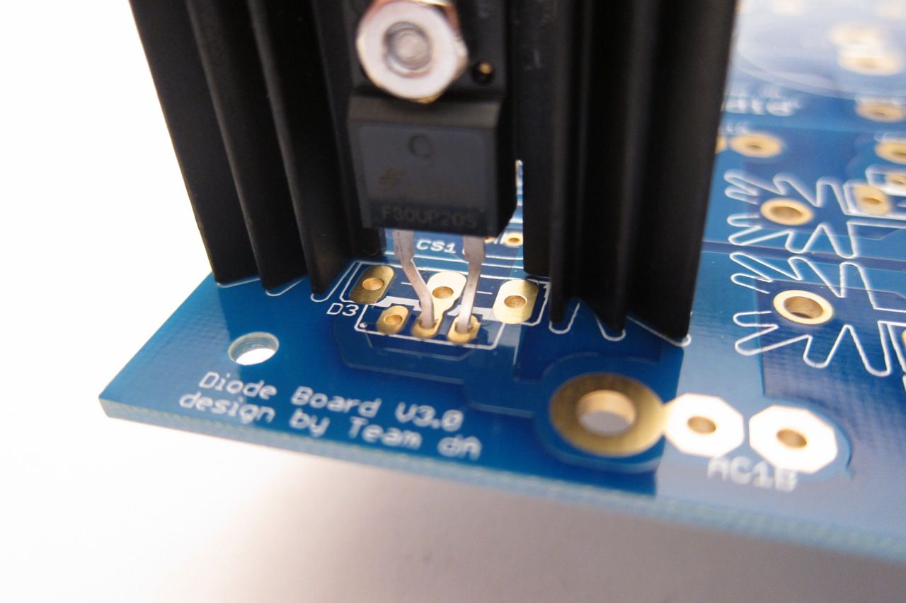
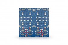
No to220 two legged diodes in the outer holes. Is that because the footprints are just designed for dual package diodes with the center as a common?
I may try building this circuit on some home made PCB, as an experiment for my creation skills. But then with possibly shrunken capacitor footprints.
No to220 two legged diodes in the outer holes. Is that because the footprints are just designed for dual package diodes with the center as a common?
I may try building this circuit on some home made PCB, as an experiment for my creation skills. But then with possibly shrunken capacitor footprints.
Requires mind reading: why did "team dA" make the choices they made? They know the answer; everyone else has no other choice except to guess.
Perhaps they felt it was a useful compromise. What they put on the PCB (a) fits TO-220 dual diodes; and also (b) fits TO-247 dual diodes; and also (c) fits TO-220 single diodes with a simple lead-bend; and also (d) fits TO-247 single diodes with a simple lead bend.
Perhaps they felt it was a useful compromise. What they put on the PCB (a) fits TO-220 dual diodes; and also (b) fits TO-247 dual diodes; and also (c) fits TO-220 single diodes with a simple lead-bend; and also (d) fits TO-247 single diodes with a simple lead bend.

Sorry if this was already explained before, I could not find. How do you connect the transformer secondary to 1A, 1B, 2A and 2B on power supply board? I believe a transformer with symmetrical output of 17-0-17V is not useful? In the photos I see a single transformer was used Do I need 17V-0V single output? In either way how do I connect to 4 separate posts on the power board?
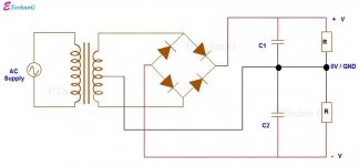
The centre tap of the transformer secondary goes to the ground of the board and each end of the secondary winding go to the AC input.
The V+ output of the rectifiers go to the V+ PS filter and the V- output of the rectifiers go to the V- PS filter.
Only one side of the rectifier board needs to be populated with diodes. Alternatively a bridge rectifier may be used in place of the discrete diodes and the rectifier board.
The V+ output of the rectifiers go to the V+ PS filter and the V- output of the rectifiers go to the V- PS filter.
Only one side of the rectifier board needs to be populated with diodes. Alternatively a bridge rectifier may be used in place of the discrete diodes and the rectifier board.
Attachments
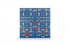
If your transformer has two identical secondary windings then both sides of the rectifier board is populated. Alternatively two bridge rectifiers may be used in place of the discrete diodes and rectifier board.
Attachments
Ben Mah I greatly appreciate all detailed information and images you provided. I am building the F5 amp, so in photos in the build guide all 8 of the diodes were in use. It was not clear in the photos but I now understand that there must have been 2 separate pairs of secondary outputs (17V) in the toroid they used then. On the other hand, in a symmetrical output transformer like I have (I considered it so (17-0-17V) since I read the voltage between 17-0 leads and 0-17 leads as 17Volts each) if I take center tap for ground and use two 17V leads to connect to 1A and 1B, wouldn’t I then be feeding 34V to PS board? Once again sorry if these questions are too naive for this forum.If your transformer has two identical secondary windings then both sides of the rectifier board is populated. Alternatively two bridge rectifiers may be used in place of the discrete diodes and rectifier board.
Apologies if this question has been asked somewhere but is there a BOM available for this? The main link in the build guide doesn't seem to work.
The BoM will be based upon the amplifier you are building (along with some personal decisions re components).
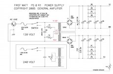
If you are looking to build a PSU for a First Watt clone, then I personally like the build guide and BoM put together here... Due to parts shortages, you may need to substitute some components, but it's an excellent reference.
If you're not building a First Watt amplifier, please provide more details of your build.
https://diyalephj.blogspot.com/
Fair point. I'm in learning mode here, having built a couple of ACAs so far but little else.
I'd like to build an F6. In my own ideal world I'd just buy all the parts and the chassis together like the ACA, and use the build guide to put it together. This project is going to be more involved than that, so I'll be forced to learn something!
Right now I'm just trying to get everything together. I can only buy the PCB, power supply board, chassis and transformers from the DIY store at this point. I'll need to acquire all the rest myself. That's a little daunting to me right now, but I'm not under any time constraints. If it takes me a few months to source the parts and gain the knowledge to do this well and safely, then so be it.
And that's about where I am!
- Jim
Hi Jim -
Wonderful! You are well on your way. All (well most) First Watt clones can utilize the same power supply. Yes, there are endless options, but my personal recommendation for a person in your shoes is to build one based upon the one that Nelson Pass uses in the commercial products. The link above is (IMO) a really fantastic way to get a basic understanding of the PSU and get it built up and ready for your F6. You can simply ignore the sections on the amplifier itself. If you've got any questions re: the F6 build itself, there's a dedicated thread. As you may have noticed, the threads can get a bit lengthy. For the F6 in particular, there are (what I'd consider) a few very simple changes (6L6 mentions at least two of them in the guide) along with a simple modification (using some LEDs in a novel application) that don't make the build any more challenging for a beginning builder, but can make your life a bit easier long term. Once you're ready to get going on that side of things post any questions over in that thread.
Keep asking any questions. Good luck; have fun; and enjoy the tunes!
- Patrick
Thanks for the encouragement AIMH. And since you asked for questions: any tips for part acquisition? Trolling through the Mouser site trying to match BOM serial numbers is going to be a new experience for me.
J
J
For the PSU, I'd start with the BoM the gents posted in the blog. I think they may have even linked a Mouser project.
For the amplifier boards...
Were I in your shoes, I would wait until the full F6 kit were back in stock in the store. Some other options below...
Getting all parts as a "kit" potentially through people that have spares around. I can maybe help you out. Not sure.
Getting everything but the boards and signal transformers from people that have spares around. Same.
Get the boards, signal transformers, JFETs and Power MOSFETs from the store. Order the rest or get from a member. This may be a nice balance. To me, it's the most attractive option short of waiting for the store to be back in stock for the full kit.
For chassis etc. Follow the link above for some excellent advice re: extra parts needed / wires etc to complete the project. They really did a super job, IMO.
https://diyaudiostore.com/collectio...s/f6-board-transformer-kit?variant=5938934404
https://diyaudiostore.com/products/matched-jfets?variant=39335247052873
https://diyaudiostore.com/collections/mosfets/products/f6-transistor-kit
As you are not in a hurry, I recommend learning the part values (as opposed to part numbers). With the current supply chain issues and usual sunsetting, exact part number matches may not be possible. Learning to find substitutes is invaluable.Thanks for the encouragement AIMH. And since you asked for questions: any tips for part acquisition? Trolling through the Mouser site trying to match BOM serial numbers is going to be a new experience for me.
J
Yes the third option is where I'm at. I've got everything the store can sell me short of the non-transformer PSU parts. I don't have the chassis yet but I was waiting on that until I could source everything else.
And thank you, I hadn't seen that blog before. I'll have fun reading it. I assume the Aleph J is pretty similar to the F6, or at least close enough that I can pick up the lion's share of what I need to know while I figure out a parts solution. Many thanks!
J
And thank you, I hadn't seen that blog before. I'll have fun reading it. I assume the Aleph J is pretty similar to the F6, or at least close enough that I can pick up the lion's share of what I need to know while I figure out a parts solution. Many thanks!
J
I'm bringing back a very old quote for the v3 PSU boards.
To clarify, can I use the store boards for two single-rail supplies? I am looking for PCB options to add capacitance after a +27VDC SMPS for LuFo monoblock builds.
To clarify, can I use the store boards for two single-rail supplies? I am looking for PCB options to add capacitance after a +27VDC SMPS for LuFo monoblock builds.
Ground is relative... and also where you decide it to be.
So if you were to split the PCB and make two single-rail supplies, stuff everything as labeled, but attach the output "backwards" -- what's marked as GND will be V+ and what's marked as V- will be GND.
If you stuff as labeled the lower voltage will be on the V- marked output pad and the higher voltage will be on the GND pad. (This is also true when it's a bipolar PSU...)
Your lower voltage you will call GND, and the higher voltage will be called V+ .
On your suggestion, 6sX7, I did make a project out of learning the values. As a result I believe I've acquired all the right resistors, caps, and connectors. Again I have a very basic question. Looking that the build guides, I'm seeing some bare wire ground connections. What gauge copper wire do you suggest for those?
- Home
- Amplifiers
- Power Supplies
- diyAudio Power Supply Circuit Board v3 illustrated build guide