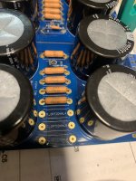
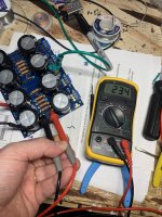
The bridge outputs show 25VDC when hooked up to the inputs of the board. Using a DMM I’m measuring. I’m also showing 25VDC across c1 c2 r1 r2 r3 r4 and r10….🤔Absolutely not. Just think how much current would need to flow to support that 🙂 Over 50 amp.
There should be no voltage across those resistors with no load attached to the board.
25 volts across C1 and C2 and R10 is correct.
You should have that same voltage across C5 and C6
If you really have got 25 volt DC across R1,2,3 and 4 then they are not 0.47 ohm resistors. Switch OFF, take one out and measure it. They would have to be something like 470k or 4.7meg to give that voltage across them. Anything lower would charge C5 and C6 up.
If you can measure 25 volts across any of those resistors then they can not be 0.47 ohm. Does that make sense 🙂 The current flow would be massive.
And just to be clear, when we say 'across' that means one meter lead on one end of the resistor and the other meter lead on the other end of the resistor.
And just to be clear, when we say 'across' that means one meter lead on one end of the resistor and the other meter lead on the other end of the resistor.
If you measure the resistance in circuit it should appear as an almost dead short, and that would be correct.
Yes the ohms law equation makes sense. And yes that’s how I was measuring them.If you can measure 25 volts across any of those resistors then they can not be 0.47 ohm. Does that make sense 🙂 The current flow would be massive.
And just to be clear, when we say 'across' that means one meter lead on one end of the resistor and the other meter lead on the other end of the resistor.
You need to measure the resistance for real then. Take one out that you know for sure had 25v across it and measure its value. You can just lift one end to isolate it.
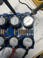
Also and with the power OFF just check there are no shorts across C5 and C6. If there were then that could have popped the resistors I suppose.
Have to leave it for tonight but I'll be interested what you find.
Also and with the power OFF just check there are no shorts across C5 and C6. If there were then that could have popped the resistors I suppose.
Have to leave it for tonight but I'll be interested what you find.
It has to open circuit then or they are not what they seem.
Check for shorts on the output side as in post #1927 above 🙂
It can't be anything else, either the parts are incorrectly marked (not 0.47 ohm) or a dead short on the output killed them... but you would think you would see/smell some burning if that happened.
Check for shorts on the output side as in post #1927 above 🙂
It can't be anything else, either the parts are incorrectly marked (not 0.47 ohm) or a dead short on the output killed them... but you would think you would see/smell some burning if that happened.
Ok I lifted one leg of one of the .47R resistors that had 25VDC across it and i can’t get a reading on DMM on it, not even continuity?? Did it burn out and go to infinite resistance?
Last edited:
Did you measure the resistors before you installed them? I always do. If you didn't, then you won't know whether it was defective to start with or it became defective during installation or use.
You need to check all of the 0.47R resistors.
You need to check all of the 0.47R resistors.
Ok got the negative rail to work!! I just shorted 2 of the unused .47R spots with wire. I’m guessing I had no continuity across the .47R path. Seems more likely that I burned them out somehow than they are all defective…
thanks to everyone who helped this clueless CPA learn how to troubleshoot a power supply!! This is a great community.
thanks to everyone who helped this clueless CPA learn how to troubleshoot a power supply!! This is a great community.
Attachments

👍 so its working.
Only you know if you might have zapped it. Always be aware that scope leads can create a short either from one channel ground lead to the other or via any scope lead and a mains ground route.
Only you know if you might have zapped it. Always be aware that scope leads can create a short either from one channel ground lead to the other or via any scope lead and a mains ground route.
Don’t forget you have now de facto bypassed your 0R47 resistors by jumpering the R6-7 spots. I recommend you replace the defective resistors/resolder bad resistor joints, and remove the jumpers. But rereading your post it seems this is your intention anyhow 🙂Ok got the negative rail to work!! I just shorted 2 of the unused .47R spots with wire. I’m guessing I had no continuity across the .47R path. Seems more likely that I burned them out somehow than they are all defective…
thanks to everyone who helped this clueless CPA learn how to troubleshoot a power supply!! This is a great community.
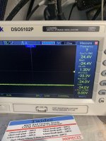
not familiar with your scope. But does it not show only 1V2 peak to peak? Cyclic RMS is 24V4. But how many volts is «normal» RMS? What does your DMM show?
Regards,
Andy
I think I must have had a short from the scope lead to mains ground. I have since watched several YouTube videos on this topic that I should have watched before I started the build 🤣👍 so its working.
Only you know if you might have zapped it. Always be aware that scope leads can create a short either from one channel ground lead to the other or via any scope lead and a mains ground route.
DMM shows the correct 24vdc. I think the pk-pk v on scope is rippleDon’t forget you have now de facto bypassed your 0R47 resistors by jumpering the R6-7 spots. I recommend you replace the defective resistors/resolder bad resistor joints, and remove the jumpers. But rereading your post it seems this is your intention anyhow 🙂
not familiar with your scope. But does it not show only 1V2 peak to peak? Cyclic RMS is 24V4. But how many volts is «normal» RMS? What does your DMM show?
Regards,
Andy
Its easily done 🙂
For ripple you need the scope on AC coupling to block the DC shift but the ripple should be pretty much non existent with no load on the rail.
For ripple you need the scope on AC coupling to block the DC shift but the ripple should be pretty much non existent with no load on the rail.
This is a pretty long thread 😉
By chance has anyone come up with a calculator of sorts to work out the various values? If not how hard do folks think it would be? ( I'd be happy to help )
I have 2 power supplies that I want to make. One is 24v for the ampcamp amp and the other is a 44v dual rail for an M2x 😉
By chance has anyone come up with a calculator of sorts to work out the various values? If not how hard do folks think it would be? ( I'd be happy to help )
I have 2 power supplies that I want to make. One is 24v for the ampcamp amp and the other is a 44v dual rail for an M2x 😉
What do you mean by the various values?
Transformer secondaries = Rail Voltage/1.414
Filter caps VDC > Rail Voltage.
Transformer VAC > .5 x Expected Current Draw x Secondary Voltage
Rectifiers > 35 Amp, 200V
Are there other values you're looking for?
Transformer secondaries = Rail Voltage/1.414
Filter caps VDC > Rail Voltage.
Transformer VAC > .5 x Expected Current Draw x Secondary Voltage
Rectifiers > 35 Amp, 200V
Are there other values you're looking for?
- Home
- Amplifiers
- Power Supplies
- diyAudio Power Supply Circuit Board v3 illustrated build guide