read like he had trimmed it and retried.That could do it - a short to ground.
how many spacers are you using and how much space between the board and the "tray". Wondering if any sag causing something to touch.
Check that the secondary winding wires are correct. Set a multimeter to resistance and measure the resistance of each secondary pair. Since both secondaries have blue-green wires, the wires can get mixed up. A correct secondary wire pair would measure near zero resistance.

I have an AN-6224 600VA 24v transformer. I read on another post that the fuse calc is:
VA of xformer/ mains voltage = Fuse rating
so for me that’s 600/120=5A
https://www.diyaudio.com/community/threads/f5-turbo-fuse-question.363234/post-6417327
VA of xformer/ mains voltage = Fuse rating
so for me that’s 600/120=5A
https://www.diyaudio.com/community/threads/f5-turbo-fuse-question.363234/post-6417327
What Ben Mah said. And…
I think on the 1st post, 6L6 had recommended the use of insulators (Keratherm or equivalent) between the rectifiers and heatsinks. Without the thermal insulators, the heatsinks can be live.
Others have already mentioned the use of proper spacer height to ensure the bottom of the pcb doesn’t touch the baseplate.
You should shut the unit off, completely unplug from mains AC, let the caps discharge, and then check with a multimeter for any and all shorts. There is a short somewhere.
Best,
Anand.
Winner winner. Thank you!Check that the secondary winding wires are correct. Set a multimeter to resistance and measure the resistance of each secondary pair. Since both secondaries have blue-green wires, the wires can get mixed up. A correct secondary wire pair would measure near zero resistance.

Hi all,
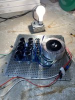
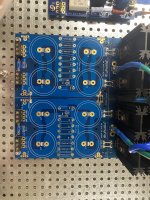
I've completed* my F5T build using the Universal PSU's and have a head scratcher. I'm getting a hum/buzz from one of the toroids, which I think I've isolated to it's respective PSU PCB. The solution's I've tried (without success) to this point include:
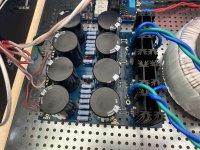
My assumption is that it's a grounding issue, but I'm open to suggestions. Below are some pics of the PCB for reference.
Thanks in advance!
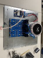
I've completed* my F5T build using the Universal PSU's and have a head scratcher. I'm getting a hum/buzz from one of the toroids, which I think I've isolated to it's respective PSU PCB. The solution's I've tried (without success) to this point include:
- Swapping the Transformer
- Inserting a DC Blocker Between Mains and Amp
- Re-soldering Ground Links and Capacitors
My assumption is that it's a grounding issue, but I'm open to suggestions. Below are some pics of the PCB for reference.
Thanks in advance!
Attachments
Asking for clarification.
The transformer itself buzzes?
If so, would mean loose winding or pulling too much current thru the transformer.
What VA is it rated for?
When you say you swap transformers, does the buzz follow the transformer or does it stick with the transformer hooked up to the particular PSU board?
The transformer itself buzzes?
If so, would mean loose winding or pulling too much current thru the transformer.
What VA is it rated for?
When you say you swap transformers, does the buzz follow the transformer or does it stick with the transformer hooked up to the particular PSU board?
Last edited:
Thanks for the quick response. Yeah the transformer itself is buzzing...but only when connected to the PSU PCB. It's the antek AN-6224. 600VA 24v secondary's. I have 8x 50V capacitors in the PCB.Asking for clarification.
The transformer itself buzzes?
If so, would mean loose winding or pulling too much current thru the transformer.
What VA is it rated for?
I tried swapping a transformer from my other identical (non-buzzing) system...same result. So I don't think the transformer is defective.
Would a faulty diode (TO-220) cause a hum? Just thinking out loud as I've already tried re-connecting the ground links and capacitors without luck.Thanks for the quick response. Yeah the transformer itself is buzzing...but only when connected to the PSU PCB. It's the antek AN-6224. 600VA 24v secondary's. I have 8x 50V capacitors in the PCB.
I tried swapping a transformer from my other identical (non-buzzing) system...same result. So I don't think the transformer is defective.
If'n I'm tracking, you disconnected the diode board from the filter board and still get the buzz?
Are the diodes isolated from the sinks?
If not, is there something causing a ground connection to a sink?
No blown fuses and PCB is intact (i.e. I didn't break off the diode board). I tried to re-solder the ground links and capacitors to see if there was a poor connection but that didn't fix it.
My other thought was that there was an issue with the TO-220 diodes, but I didn't want to go down a rabbit hole if faulty diodes wouldn't contribute to hum/buzz.
I haven't tried lifting the ground. Wouldn't that cause a short?
1. Did you check the secondary leads are paired up correctly?
2. Does the buzzing change on which set of diodes the secondary leads hook up to?
3. Does the buzzing occur when only the diode section is hooked up? (no caps/resistors in the path?)
Probably asking too specific questions as opposed to giving good troubleshooting advice. Idea is to back down to the simplest circuit and slowly add until the buzz starts.
Lifting the ground won't cause a short, the exact opposite. Will allow the circuit to come to a steady state, reducing current draw. Just remember that if the caps are in the circuit they will charge up and will need to be discharged before handling.
Yes. But (always the caveat) realize that the voltage will have nowhere to go and handle accordingly.
In troubleshooting, I'd back down to the simplest configuration and slowly add until the buzz comes back:
1. transformer only
2. transformer + full wave bridge
3. transformer + fwb + filter
4. transformer + fwb + filter + ground
5. transformer + fwb + filter + grnd + signal boards
Ground doesn't need to be hooked up for this. Just remember that with the filter section in the circuit and no ground, the caps will get charged up and will need to be discharged before handling.
Well I've got some work to do. Appreciate the suggestions. I'll post the findings.Yes. But (always the caveat) realize that the voltage will have nowhere to go and handle accordingly.
In troubleshooting, I'd back down to the simplest configuration and slowly add until the buzz comes back:
1. transformer only
2. transformer + full wave bridge
3. transformer + fwb + filter
4. transformer + fwb + filter + ground
5. transformer + fwb + filter + grnd + signal boards
Ground doesn't need to be hooked up for this. Just remember that with the filter section in the circuit and no ground, the caps will get charged up and will need to be discharged before handling.
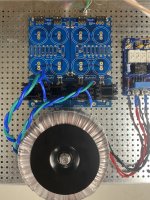
1. PassYes. But (always the caveat) realize that the voltage will have nowhere to go and handle accordingly.
In troubleshooting, I'd back down to the simplest configuration and slowly add until the buzz comes back:
1. transformer only
2. transformer + full wave bridge
3. transformer + fwb + filter
4. transformer + fwb + filter + ground
5. transformer + fwb + filter + grnd + signal boards
Ground doesn't need to be hooked up for this. Just remember that with the filter section in the circuit and no ground, the caps will get charged up and will need to be discharged before handling.
2. Pass
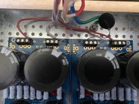
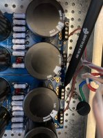
desoldering the capacitors, resistors and LEDs took some time, but I was able to get everything out and cleaned to do steps 1 & 2. I hear buzz, but it’s only audible if my ear is a few inches away (which I assume is inherent for toroids). For context, I could hear the buzz before standing 10 feet away.
On to step 3…
Attachments
- Home
- Amplifiers
- Power Supplies
- diyAudio Power Supply Circuit Board v3 illustrated build guide