Is it Ok to mount the boards the power supply boards with the rectifier portion still in tact to the front chassis panel like in the picture I included or should I have the rectifiers mounted to the base for maximum heat sinking of the rectifiers?
Attachments
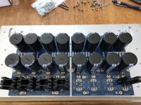
The heatsinking is 100% via the PCB mounted heatsinks and has nothing to do with what the board is mounted to.
That said, I dont think you can assemble the amp like that (PSU on front plate) with the rectifier section attached... You'll need to see if it clears the chassis floor.
That said, I dont think you can assemble the amp like that (PSU on front plate) with the rectifier section attached... You'll need to see if it clears the chassis floor.
That’s a good point I’m not sure about that either. I don’t have the floor for the 5U case, it was shipped missing. When it arrives I’ll need to look into that. Thanks
DiyAudio Universal Power Supply v3 - Correct toroidal transformer?
Hi - I would like to confirm the correct Antek Part Number for the Toroidal Transformer used in the DiyAudio Universal Power Supply v3. This is for use with the F6 amplifier. I am in Australia using 230VAC. I see references to AS-4218 (shielded) and AS-4220 (shielded). Both out of stock from what I can see. I can't see the Antek Part Number in the schematics (F6 or UPSv3) or in the build guides or in the parts list for the UPS v3. Much appreciated. Geoff
Hi - I would like to confirm the correct Antek Part Number for the Toroidal Transformer used in the DiyAudio Universal Power Supply v3. This is for use with the F6 amplifier. I am in Australia using 230VAC. I see references to AS-4218 (shielded) and AS-4220 (shielded). Both out of stock from what I can see. I can't see the Antek Part Number in the schematics (F6 or UPSv3) or in the build guides or in the parts list for the UPS v3. Much appreciated. Geoff
The heatsinking is 100% via the PCB mounted heatsinks and has nothing to do with what the board is mounted to.
That said, I dont think you can assemble the amp like that (PSU on front plate) with the rectifier section attached... You'll need to see if it clears the chassis floor.
6L6 is right as always. For what it’s worth I considered mounting the whole shabang on the front plate. Well vertically that is impossible or at best extremely close. You could either split the boards or fllip it 180 degrees, if only one board and you are OK with the assymetry. I would try to find a way to put the boards on the chassis floor, and if you split the rectifiers from the PSU section beware those connections will have a lot of ripple on them.
Andy
melbourne - You can use a AS-3218. They're in stock. FWIW, I've often read that 300VA transformers were used in production First Watt amps if that eases any concerns.
You don't see part numbers b/c there's a large variety of transformers from Antek and other manufacturers that will work wonderfully.
You don't see part numbers b/c there's a large variety of transformers from Antek and other manufacturers that will work wonderfully.
I jumped right on the AN-5218 but I’m sure that was overkill. Being my first build of NP design I figured it can’t hurt. Performance of F6 is outstanding.
Universal Power Supply v3 - Parts
Hi - Thanks for the replies which state that the Antek AS-3218 is ok to use as is the AS-4218. This would be well worth adding to the UPS v3 Build Notes. I built the fantastic ACA 1.6 and am very very happy with it but I am looking for a challenge and the F6 certainly IS a challenge in comparison! I am having great difficulty understanding the Bill of Materials spreadsheet for the UPS v3. In the PSU v3 Build Guide there is a photo of the 2 PCBs and ALL the parts required are arranged around those 2 boards. I count 42 parts (not counting the 2 x PCBs) in the photograph. But in the BoM spreadsheet there are 35 ROWS with Digi-Key part numbers (8 rows are orange, 2 rows are green, 20 rows are purple, 2 rows are blue & 3 rows are pink). So it appears that 7 rows or part numbers are missing. I wish there was a straight forward listing of the required parts as is shown in the excellent F5 build notes. Any clarification would be greatfully received. Thanks Geoff.
Hi - Thanks for the replies which state that the Antek AS-3218 is ok to use as is the AS-4218. This would be well worth adding to the UPS v3 Build Notes. I built the fantastic ACA 1.6 and am very very happy with it but I am looking for a challenge and the F6 certainly IS a challenge in comparison! I am having great difficulty understanding the Bill of Materials spreadsheet for the UPS v3. In the PSU v3 Build Guide there is a photo of the 2 PCBs and ALL the parts required are arranged around those 2 boards. I count 42 parts (not counting the 2 x PCBs) in the photograph. But in the BoM spreadsheet there are 35 ROWS with Digi-Key part numbers (8 rows are orange, 2 rows are green, 20 rows are purple, 2 rows are blue & 3 rows are pink). So it appears that 7 rows or part numbers are missing. I wish there was a straight forward listing of the required parts as is shown in the excellent F5 build notes. Any clarification would be greatfully received. Thanks Geoff.
Geoff
The BOM is complete.
The image from 6L6 shows every single part _except_ the input- and output-snubbers.
Research „quasimodo“ and the transformer you‘ll use for more.
Did you you account for hoe many parts the bom mentions (like, _8_ capacitors 15000 uF etc)?
Furthermore, you will need either the blades („Snap-On board connectors“) or the „Screw-Type Vertical Bboard Connectors“ from the pink row in the bom.
Another thing to consider is if you want to build the rectifier-part or use the diode-block... Look up the amplifier-build-guides for illustrations...
And finally, here’s a great tutorial/introduction about PSU‘s. Read it [emoji6]
Hi Geoff,
I think all new builders go through a lot of same struggles at first. I know I sure did. A few things you may or may not know.
Enjoy the build process and the fun of learning. It's a blast. Most importantly, enjoy the F6. It's incredible.

I think all new builders go through a lot of same struggles at first. I know I sure did. A few things you may or may not know.
1) This community is absolutely amazing. Every question I had was answered quickly and courteously.
2) BoMs are not always lists with specific part numbers. Parts go obsolete all the time or sadly may not be in stock from your favorite supplier. I just had that issue yesterday ordering some parts. So, the BoM and/or the schematic will give you enough information to order an appropriate part with the correct specifications.
3) Once you build one "First Watt" power supply, it will work with all the First Watt amps sold in the store (and possibly many more). The biggest investment is usually your chassis, PSU, connectors etc. Once you've built your F6, you can swap out amp boards (relatively cheaply) to have the fun of building a new amp w/o all the expense. I love that concept.
4) The board is (as named) Universal. So, there are some options to choose. First is whether you want to use individual rectifiers on the board or use monolithic rectifiers. If you don't know what that means yet, I'd encourage going with monolithic rectifiers for your first build. If it adds any comfort, I know at least a few of the production First Watt amps use them. See below.
5) Since all the First Watt amplifiers use the same PSU, I'd encourage you to check out this blog written by a new builder for new builders. It has a full bill of materials for literally everything you need for your PSU including nuts and bolts, wiring etc. etc. They use the monolithic rectifiers. They also give some tips that will apply to building any amp, including the F6. NOTE: They show the wiring for 120VAC mains. So, before you wire your transformer primaries to your mains connection, please ask the forum if you have any confusion/questions re: fuse values, wiring, thermistors, etc.
DIY Aleph J: A Build Guide
6) You don't need a snubber, but if it provides peace of mind, you can find the values for your parts in the thread linked below most likely. If you can't find it for the transformer you've ultimately chosen, just ask. Someone may be able to guide you. If not, just leave it out. You can always add it later.
Quasimodo results (ONLY)
7) After you get your first one built, a lot of this will seem second nature.
Enjoy the build process and the fun of learning. It's a blast. Most importantly, enjoy the F6. It's incredible.
I have found reading as much as I can of the different amp builds really helped me to understand..my own experience was just taking my time. Leftear & inmyhead are right on with their direction. I built the F6 and it is very good sounding & was fun to build. Enjoy
Last edited:
Thanks for your replies especially ItsAllInMyHead. Based on your encouraging replies I have ordered the F6 boards and components and JFETS and an AnTek Inc AS-4218 toroidal. As suggested I will go for the Monolithic rectifiers (whatever they are...to be researched!). I have had a look at the Blogg you suggested and it looks good; it will take me many hours to read it and to digest it). I dont need a Snubber you say but as above I have no idea what it is so more Googling is required. The BoM still looks to be a real pain in the 'you know where' but I will persevere. I am confused about the Schematic for the Universal Power Supply v 3. The Build Notes at about page 2 has a diagram which includes a toroidal transformer but I assume this is an older UPS? Because Jason has posted a Schematic which to my untrained eye looks completely different. I assume this is for the UPS v3? It does not include the toroidal transformer. I will try to post/attach these 2 Schematics if I can but I would very much appreciate clarification please. With thanks Geoff Lee.
Attachments
The input snubber...
... does not affect your listening experience.
... it does help your transformer when you turn it on. That is, the first few sinuswaves (of the current) do swing very high until it settles down to the expected range. These swings are a bit stressful for the transformer. A properly configured input snubber brings this very first swings down very elegantly. Thus, the transformer is less stressed.
I can‘t explain it any better, sorry.
I‘d recommend to first read a little into the quasimodo-thread, find the pictures, and then research the proper values required by your. Antek...
(Spoilers:
Simple, no-math transformer snubber using Quasimodo test-jig
Quasimodo results (ONLY)
https://www.diyaudio.com/forums/power-supplies/313202-quasimodo-results-2.html#post5692124
)
Last edited:
Thanks for your replies especially ItsAllInMyHead. Based on your encouraging replies I have ordered the F6 boards and components and JFETS and an AnTek Inc AS-4218 toroidal. As suggested I will go for the Monolithic rectifiers (whatever they are...to be researched!). I have had a look at the Blogg you suggested and it looks good; it will take me many hours to read it and to digest it). I dont need a Snubber you say but as above I have no idea what it is so more Googling is required. The BoM still looks to be a real pain in the 'you know where' but I will persevere. I am confused about the Schematic for the Universal Power Supply v 3. The Build Notes at about page 2 has a diagram which includes a toroidal transformer but I assume this is an older UPS? Because Jason has posted a Schematic which to my untrained eye looks completely different. I assume this is for the UPS v3? It does not include the toroidal transformer. I will try to post/attach these 2 Schematics if I can but I would very much appreciate clarification please. With thanks Geoff Lee.
Hi, Geoff!
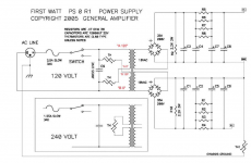
The schem is for a FW power supply by Nelson Pass. The tranny is reflected in those waveformed lines in the middle there.
The universal PSU can be used to make a fitting supply iaw that schematic.
Cheers,
Andy
Geoff, what you see in the second schematic (PSU v3.0) is the right hand side of the FW full power supply scheme in the first one (everything to the right side of the transformer).
Now, the left side of the v3.0 schematics is for the discreete diode bridges that you will not use. You will use monolitic rectifiers like these:
https://eu.mouser.com/ProductDetail/625-GBPC3502-E4/
Also, you will not need the R11-12 and C17-18 what makes the output snubbers that are not needed for F6. And you will not use the optional resistors.
Now you can see that the schematics are quite identical.
One more note. In FW schematic R9-10 (bleeder resistors) are indicated as 2.2K, but in the PSU BOM you'll see 4.7K-22K. That's ok, anyting will do. The higher the value, the longer it will take the capacitors to discharge without the load when you switch the power off. But that does not matter much.
Hope this helps. I remember myself building the first amp 🙂
-Alvis
Thanks for your replies especially ItsAllInMyHead. Based on your encouraging replies I have ordered the F6 boards and components and JFETS and an AnTek Inc AS-4218 toroidal. As suggested I will go for the Monolithic rectifiers (whatever they are...to be researched!). I have had a look at the Blogg you suggested and it looks good; it will take me many hours to read it and to digest it). I dont need a Snubber you say but as above I have no idea what it is so more Googling is required. The BoM still looks to be a real pain in the 'you know where' but I will persevere. I am confused about the Schematic for the Universal Power Supply v 3. The Build Notes at about page 2 has a diagram which includes a toroidal transformer but I assume this is an older UPS? Because Jason has posted a Schematic which to my untrained eye looks completely different. I assume this is for the UPS v3? It does not include the toroidal transformer. I will try to post/attach these 2 Schematics if I can but I would very much appreciate clarification please. With thanks Geoff Lee.
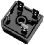
"Monolithic" bridge is not a great term - it came into use simply because there are 4 rectifiers in a single package. The ones typically used in FW type class A amps look like the picture below. Here is a link to an example: https://www.mouser.com/ProductDetai...child/GBPC3502/?qs=j%2BucPx4PkG66Qy0UInQzXQ==
BTW - I prefer these to the ones the snap-off boards in the UPS were designed for. Simple, chassis mount, Faston tabs, cheap and reliable.
Attachments
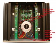
Hi Patrick (itsAllInYourHead)? - I tried to send this in a PM but the address I used was wrong apparently. I consider that I know next to nothing about electronics. The replies I get may as well be in French because I have to look up Google for an explanation to every second word or term! And that takes hours! I have a little experience. I did the Overnight Sensations speakers and soldered up the crossovers. Ditto the Sunflower Redux tower open baffle speakers and I helped a mate who built 4 x Modulus-86 mono blocks and I built the Amp Camp Amp on my own which worked first time! BUT nothing has prepared me for doing the Universal Power Supply!!! So basic and simple suggestions are welcome. Nothing anyone says will be taken as an affront! I have spent the morning reading up on toroidal transformers and how to wire them up and I am making progress but some way to go of course. On the Universal Power Supply PCBs I assume from the replies I have that I snap off the bottom 1/4 ie the diode section and instead use 2 x Monolithic Rectifiers? I cannot find a high res photo of a F6 fully built up so I am using one of the F5. Which is attached. Cheers Geoff Lee, Melbourne Australia.
Attachments
Hi Geoff -
No worries. I got a message, but it was just a reply with my note quoted.
tl;dr - you'll really enjoy the amp when you're done. We've all been in your shoes at one point or another.
When you get all your boards and parts and follow along in the blog, things will start to look a lot more familiar for the PSU. The F6 build guide has some nice photos that should make it easier for the amp boards.
Just ask questions along the way if anything gets confusing.
Patrick
- Home
- Amplifiers
- Power Supplies
- diyAudio Power Supply Circuit Board v3 illustrated build guide