You might need to change the zener diode value if you need more bias, but that’s always on a case-by-case basis and has more to do with the Vgs of your mosfets than anything else.
With a 20v transformer you’ll have rail voltages about 1.5v more than what most builders have. (I.E., you’ll have very close to 24v under load, people with 18V transformers have 22.5v or a bit more)
hello sir. I just got a bunch of parts for my f6 build. I got a 400 va transformer with 18v secondarys. this xfrm came with a purple wire that is wired to a static shield. Am I supposed to ground this purple wire?
also I used 90 ohm resistors for r11 and r 12. this should work well.
now the diode
Hello again, another step I dunno wether it's a pitfall...
I tried to have a basic feeling of why to choose which diode, but mouser plays cat with me (think Tom & Jerry)
then 6L6 puts it that way:
perfect! I went to mouser and found:
FEP30DP = N/A (Mouser Part No = Not Assigned)
FEP30DP-E3/45 = CHF 2.22 /unit
and then there's
TO-247-3 (CHF 6.21 = expensive! better values? faster, "tougher"... but worth it?)
TO-247 (CHF 1.73 = ok...)
Can I go with them?
How do I interpret the values / codes of these buggers? (faster ~= better etc...)
Thanks again!
david
Hello again, another step I dunno wether it's a pitfall...
I tried to have a basic feeling of why to choose which diode, but mouser plays cat with me (think Tom & Jerry)
then 6L6 puts it that way:
Buy the FEP30DP
perfect! I went to mouser and found:
FEP30DP = N/A (Mouser Part No = Not Assigned)
FEP30DP-E3/45 = CHF 2.22 /unit
and then there's
TO-247-3 (CHF 6.21 = expensive! better values? faster, "tougher"... but worth it?)
TO-247 (CHF 1.73 = ok...)
Can I go with them?
How do I interpret the values / codes of these buggers? (faster ~= better etc...)
Thanks again!
david
Last edited:
The E3 is a certification for lead-free components that specifies low growth of tin whiskers on the leads. You can use those just fine.
From the datasheet:
Terminals: Matte tin plated leads, solderable per J-STD-002 and JESD22-B102E3 suffix meets JESD 201 class 1A whisker test
From the datasheet:
Terminals: Matte tin plated leads, solderable per J-STD-002 and JESD22-B102E3 suffix meets JESD 201 class 1A whisker test
Thank you, silasmellor! 
Next one is the heatsink:
Mouser either wants meto be happy with a height of: 25.4 mm (or buy 5000 min.)
is this sufficient?
Next one is the heatsink:
Mouser either wants meto be happy with a height of: 25.4 mm (or buy 5000 min.)
is this sufficient?
Mouser either wants meto be happy with a height of: 25.4 mm (or buy 5000 min.)
is this sufficient?
Sorry, please ignore the previous post, I found it myself. Mouser isn't all too consistent in its product-search. grmbll.
Transformer -> Diode board
Hello All,
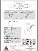
I have been searching for where to connect the secondaries from the transformer on the diode board. I have seen lots of great photos from other PSU’s, but I can not get a clear view of where to connect the plus or minus.
On the diode board I have the following connections, where I think the following secondaries from the transformer must go, is this correct? (Please see the attachments for the data sheet and if photos).
• AC1A (Yellow 0v)
• AC1B (Red 18v)
• AC2A (Grey 0v)
• AC2B (Blue 18v)
Thanks in advance!
Regards,
Koos
Hello All,
I have been searching for where to connect the secondaries from the transformer on the diode board. I have seen lots of great photos from other PSU’s, but I can not get a clear view of where to connect the plus or minus.
On the diode board I have the following connections, where I think the following secondaries from the transformer must go, is this correct? (Please see the attachments for the data sheet and if photos).
• AC1A (Yellow 0v)
• AC1B (Red 18v)
• AC2A (Grey 0v)
• AC2B (Blue 18v)
Thanks in advance!
Regards,
Koos
Attachments
Correct! Your secondaries are AC so no +/-
@silasmellor, thank you!
Ah yes, AC is 18v on all secondary wires!
Does this actually mean that it doesn’t matter where to connect the secondaries, either side of the diode board is ok?
As long as you keep the pairs on the same half as you specified it shouldn’t matter.
@Silasmellor,
Ok, that’s clear! Thank you. 🙂
Good day again!
Now I got the FEP30DP-E3/45 and its heatsinks (38 mm high)...
If I correctly followed the threads, I'm better off with a electric insulation, and must use some kind of thermal "connection", right?
Is it best to use plain keratherm? Or there's Aavid's "Thermal Interface Products Insulator, Aluminum Oxide Ceramic for TO-247", with 18.01 W/(m°C) @ 25°C, which would require additional goop?
Thank you!
david
Last edited:
input snubber, this time
Hi again.
I'm slow, but steadily approaching order-state.
Regarding the input snubber, which values (for the toroid I will get) are published over @ Quasimodo, but I also read that the snubber reduces the voltage to a certain amount (1-2%?).
And as an alternative, some have built soft-start-devices, while precious ZM recommends a simple solution using a relais...
Is there any visual approach to that (ZM-way)?
Thanks again!
david
No DC voltage output from diode board
Hello All,
I am making good progress with my FW F6 build, really enjoying it!
But now I ran into a showstopper when powering up the PSU.
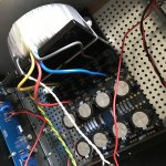
I get 230V AC to the transformer, and I measure the following at the diode board inputs:
- Between AC1A and AC1B: 18V AC
- Between AC2A and AC2B: 18V AC
- Between GND and AC1A: 36V AC
- Between GND and AC1B: 20V AC
- Between GND and AC2A: 36V AC
- Between GND and AC2B: 20V AC
When I measure at the diode board outputs:
- V+ : 0V DC
- V- : 0V DC
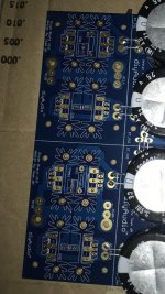
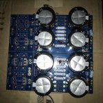
Could there be something wrong with my diode board, did I solder the diodes at the wrong connections?
Please see the photos attached for reference?
Any help is much appreciated, questions are welcome. 🙂
Thanks in advance.
Koos
Hello All,
I am making good progress with my FW F6 build, really enjoying it!
But now I ran into a showstopper when powering up the PSU.
I get 230V AC to the transformer, and I measure the following at the diode board inputs:
- Between AC1A and AC1B: 18V AC
- Between AC2A and AC2B: 18V AC
- Between GND and AC1A: 36V AC
- Between GND and AC1B: 20V AC
- Between GND and AC2A: 36V AC
- Between GND and AC2B: 20V AC
When I measure at the diode board outputs:
- V+ : 0V DC
- V- : 0V DC
Could there be something wrong with my diode board, did I solder the diodes at the wrong connections?
Please see the photos attached for reference?
Any help is much appreciated, questions are welcome. 🙂
Thanks in advance.
Koos
Attachments
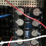
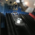
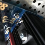
Looks like FEP30DP but according to data sheet they should be 3 legged, so must be something else. Please tell us which diodes your used. Looks like a diode polarity issue you me.
Looks like FEP30DP but according to data sheet they should be 3 legged, so must be something else. Please tell us which diodes your used. Looks like a diode polarity issue you me.
Hello Silasmellor,
Thank you for your quick reply.
I used FEP30DP-E3/45GI-ND (according to the BOM, I used the Digikey order number) and connected them according the photos in the first post of this thread.
If any other information is required please let me know!
Thank you.
Koos
Looks like FEP30DP but according to data sheet they should be 3 legged, so must be something else. Please tell us which diodes your used. Looks like a diode polarity issue you me.
I cut the middle leg off, as was done in the photos of the build post.
Koos
There is your problem, 3 legged diodes should use all the legs, the ones in the guide are 2 legged ones.
- Home
- Amplifiers
- Power Supplies
- diyAudio Power Supply Circuit Board v3 illustrated build guide