One, or two?
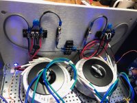
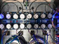
Completed testing and reset of bias voltages and DC offset after conversion from single 400VA transformer/PS board to dual mono 2x200VA transformers and addition of 2nd PS board yesterday.
Everything fit into the 5U chassis quite nicely. Didn't have to do a bit of tapping, only drilling was for the grommets in the holey base plate.
Mains voltage is nominally 245VAC.
Amp boards are Aleph J.
Got the 1rst listen in last night and I was stunned by the improvement in SQ.
Listened to 6 CD's, stopped at midnight 'cuz I couldn't keep my eyes open any longer.
Will get some more time in before trying to describe in greater detail the difference PS mod has made, over in the Aleph J thread.
For now, I mainly wanted to illustrate how well the diyAudio store components mesh together.
Attachments
Mains voltage is nominally 245VAC.
I know Arkansas is an interesting state based on my few visits, but ... y'all really are "off the grid". 😀
 Assuming you've relocated.
Fantastic looking update. Looking forward to hearing more about impressions.
Input and output snubbers - do you mean snubbers between the rectifiers and the first capacitors and snubbers after the final capacitors? If yes, then most diyAudio First Watt amplifier builders do not put them in their supplies. Note that the typical First Watt power supply does not include those snubbers.
As for the Quasimodo derived snubber between the transformer secondary and rectifiers, many builders, me included, do put those in. The values that you noted agree with the values shown here Quasimodo results (ONLY) in post #17. Mark Johnson recommends Epcos B32529 series metallized film capacitors and 0.5W metal film resistors.
B32529C0474J289 EPCOS / TDK | Mouser Canada
B32529C0332K189 EPCOS / TDK | Mouser Canada
For AC input safety capacitor:
ECQ-U2A332KL Panasonic | Mouser Canada
Ben, you have 2 different .0033uF capacitors listed:
B32529C0332K189 EPCOS / TDK | Mouser Canada
For AC input safety capacitor:
ECQ-U2A332KL Panasonic | Mouser Canada
Will either one work?
Thanks
I know Arkansas is an interesting state based on my few visits, but ... y'all really are "off the grid". 😀
Fantastic looking update. Looking forward to hearing more about impressions.
I'm the one "off the grid". Plain ol' crazy might be a better term.
I pulled 10AWG for 20A, 240VAC outlets behind my rack for amplifiers.
Also pulled a separate 120VAC circuit that is transformer isolated in the crawl space just below the rack.
Experimented with ungrounded conductor supply AC a few years back and convinced myself that my equipment sounded better when fed balanced, ungrounded juice. Could be AllInMyHead, though. 😀
I absolutely love it. Thanks for taking the time to explain. I incorrectly assumed that you'd relocated. 😀 Now... I need to make sure my wife's not reading over my shoulder. She's been nagging me that the kettle heats too slowly since we moved back...
I absolutely love it. Thanks for taking the time to explain. I incorrectly assumed that you'd relocated. 😀 Now... I need to make sure my wife's not reading over my shoulder. She's been nagging me that the kettle heats too slowly since we moved back...
Where from?
Kettle, eh? UK? Erin?
Ben, you have 2 different .0033uF capacitors listed:
B32529C0332K189 EPCOS / TDK | Mouser Canada
For AC input safety capacitor:
ECQ-U2A332KL Panasonic | Mouser Canada
Will either one work?
Thanks
The high-quality Polyethylene Terephthalate (PET) capacitors are for the Qausimodo (snubber capacitors)
The safety capacitor goes across the primary. Its value can be anywhere between 0.1 and 0.033uF, but it must be safety rated, at 250V AC.
"Safety Rated" = the capacitor can not become a short, it will ALWAYS lose the capacitance in case of overheating, i.e. the metalized polyester film will start developing little holes in a metallised film - therefore losing its capacitance and “self-healing” in a way that it will cool itself by losing capacitance & reducing its current, until two things happen:
the capacitance goes to almost zero
or
the root cause of the capacitor overheating, disappears by some means...
Last edited:
Where from?
Kettle, eh? UK? Erin?
We lived in Hong Kong for 4 years (over two separate assignments). INCREDIBLY bad AC noise there... I could hear my neighbors' cable TV audio carried through my AC line if I did not use proper filtering. Hum and hiss and everything in between were a constant battle.... but the kettle did heat quickly. So, we had that going for us, which was nice 😀
Long ways in miles and culturally, indeed.
1/2 voltage and ambient temps in the arctic range?
Lucky you can get water to boil at all.
AC noise is a real deal that has to be accounted for if'n you want high quality sound reproduction.
1/2 voltage and ambient temps in the arctic range?
Lucky you can get water to boil at all.
AC noise is a real deal that has to be accounted for if'n you want high quality sound reproduction.
Hong Kong to backwoods Minnesota. Now that's a move. 😉
LOL! Not quite back woods, but it certainly is a different day to day environment. <Hums Petshop Boys - Suburbia> We were here (kept our home) prior to the moves, so the acclimation wasn't too terrible coming home.
Long ways in miles and culturally, indeed.
1/2 voltage and ambient temps in the arctic range?
Lucky you can get water to boil at all.
AC noise is a real deal that has to be accounted for if'n you want high quality sound reproduction.
It's more fun to throw the boiling water into the arctic air outdoors 😀
I'm learning more and more that the PSUs and their surrounding components that provide a nice clean / non-wavering DC voltage to the amp boards is quite a challenge and very important. Great learning for me. That's also why I try to share PSUs whenever possible between amps.
The high-quality Polyethylene Terephthalate (PET) capacitors are for the Qausimodo (snubber capacitors)
The safety capacitor goes across the primary. Its value can be anywhere between 0.1 and 0.033uF, but it must be safety rated, at 250V AC.
"Safety Rated" = the capacitor can not become a short, it will ALWAYS lose the capacitance in case of overheating, i.e. the metalized polyester film will start developing little holes in a metallised film - therefore losing its capacitance and “self-healing” in a way that it will cool itself by losing capacitance & reducing its current, until two things happen:
the capacitance goes to almost zero
or
the root cause of the capacitor overheating, disappears by some means...
Hi rsaurmure,
What Extreme_Boky said.
The safely capacitor is shown on the power supply schematic connected across the power transformer primary.
If it fails, it will fail "open", not as a short as some non-safety rated capacitors may do. Failing as a short in this location is not safe as it will short circuit the AC power from your wall socket. Failing "open" means it will fail by opening and taking itself out of the circuit so electrically, it no longer exists.
Ben
Getting there - transformer question
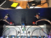
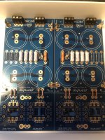
So I have been soldering away in my spare time.
Stuffed all the small components in the board, (yes I did clean up the flux) and have the capacitors in.
I am using the Antek 4218 and have a question about connecting the secondaries to the board. Does the wiring in the attached picture look correct or do the green and blue wires on one side of the board need to be reversed?
Should it be:
AC1A green from 1st secondary
AC1B blue from 1st secondary
AC2A green from 2nd secondary
AC2B blue from 2nd secondary
or
AC1A green from 1st secondary
AC1B blue from 1st secondary
AC2A blue from 2nd secondary
AC2B green from 2nd secondary
Have to pull the plug on a chassis as well. Really like the 4U Deluxe.
Thanks for your help.
Attachments

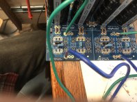
@rsaumure - your secondaries are good per your last pic.
Edited to add for clarity - Either way you noted would work fine.
Edited to add for clarity - Either way you noted would work fine.
Last edited:
Thanks, I am still trying to get my head around + rails and - rails. It just seems to me that you have a circuit - one side is positive and the other is negative.
Regards,
Regards,
Thanks, I am still trying to get my head around + rails and - rails. It just seems to me that you have a circuit - one side is positive and the other is negative.
Regards,
Well, I'm still a bit new to all this still too, but in essence, the secondaries are just the reduced AC voltage from the transformer. In this case 18VAC or so down from 110VAC or so from your wall. There is no + or - on the AC side prior to rectification. Once you've got your lovely clean 24VDC or so out of the beautiful PSU you're building (the V+ and V-), you'll really need to pay attention.
Friendly advice from another noob: color-coded wires that immediately tell you POS supply (V+), NEG supply (V-) and GND so visually you know exactly what you're looking at instinctively every time can be your best friend. Mixing up V+ and V- can lead to a non-happy event.
Enjoy the build. It's a ton of fun! 😀
I know the rail voltages are plus and minus and am still at the point for any given DC circuit you grab 1 wire and its positive and the other wire and its negative. So I guess I have a long way to go with understanding rail voltage.
You do bring up an really good point I actually had not considered in color coding the POS supply and Neg supplies. I would have not thought of that and just had a red and a white for each side.
Thank you for pointing that out and saving me from having to explain a nasty smell to my wife. You end up putting a lot of time money and effort into these projects and I would hate to see one go up in smoke (literally).
- Home
- Amplifiers
- Power Supplies
- diyAudio Power Supply Circuit Board v3 illustrated build guide