Capacitor value
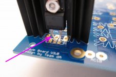
I am trying to find the value for the capacitor that goes between the thermistors on the primary side of the toroid. Is it .0033 and just a plain ceramic type, what voltage rating?
Thanks
I am trying to find the value for the capacitor that goes between the thermistors on the primary side of the toroid. Is it .0033 and just a plain ceramic type, what voltage rating?
Thanks
It's 0.0033uF (3300pF) and needs to be X1/Y2 (or better) rated for AC line use.
ECQ-U2A332ML Panasonic | Mouser
ECQ-U2A332ML Panasonic | Mouser
Power supply simulation is a great way to evaluate different power supply setups. I don't know which software you have tried but PSUD2 is the one that I use. You can easily add/delete/change configurations and then check the resultant ripple at the supply output. By trying different types (CRC, CRCRC, CLC, etc) and varying values you can get an idea of what affects ripple the most.
I tried using that simulator to figure out how to go from CRC to CRCRC and what effect it would have, but I got stuck trying to figure out how to use it, and how to enter in the GBPC3502 bridge rectifiers. I looked up the datasheet for it, the Antec AS-4218, and the caps I was using, and couldn't find the values it was asking for.
I'm a noob, and that was enough friction to convince me this isn't the best way to figure out if I would get any value from adding another RC filter to the UPS.
But I've been curious about this for a year now, googling has been next to useless for finding an answer, and I've seen people in this forum make references to turning the universal power supply into a CRCRC supply, so I'm going to go ahead and ask: what does a CRCRC version of the universal power supply look like, schematic and values-wise? I know you need to pick the R and C values carefully, to prevent voltage drop. What little poking around I did in the simulator seemed to show that an additional RC stage would drop voltage by some amount, and I don't know if that means you need to tweak the upstream CRC values to compensate, or if you just have to eat the loss.
Me, a noob, thought that just smashing in another row of R1-8 and another row of caps might work, but it might also produce the bluesmoke.
Well, yes, it will work, but what are you trying to accomplish? It’s not going to be any quieter, it won’t add any power, (it will actually lose some, as you surmise, because of the additional voltage loss...) and the standard spec PSU with 300VA transformer and (8) 15,000uF caps is already oversized for the application... 😀
Well, yes, it will work, but what are you trying to accomplish?
Nothing in particular. Just scratching a curiosity.
I tried using that simulator to figure out how to go from CRC to CRCRC and what effect it would have, but I got stuck trying to figure out how to use it, and how to enter in the GBPC3502 bridge rectifiers. I looked up the datasheet for it, the Antec AS-4218, and the caps I was using, and couldn't find the values it was asking for.
Learning is good for the brain.
When in PSU Designer II, hover your mouse pointer over a component and when the component is highlighted in a yellow box, right click and an "edit" option shows. Click on that will open a small window to enter values.
If you hover your mouse pointer over a section of the power supply and the whole section is highlighted in a yellow box, right click and a small window opens for you to choose "change", "insert", or "delete". This allows you to change, insert, or delete "C", "RC", "LC", etc.
Knowing these basic moves, you can experiment with different components and power supply layouts to see how changes affect voltages, ripple, etc.
I'm sorry but I think there's been a misunderstanding. Figuring all of that out was rather trivial. The problem is in figuring out what values to enter in for all of the fields it asks for for the following parts which are commonly used to build the UPS:
- GBPC3502 bridge rectifiers
- Antek AS-4218 transformer
- 647-LGU1V183MELC capacitors (C1-C8)
I figured a good place to start would be to model my UPS as it currently is. I don't know if modeling R9/R10 is important, but if it is it would be nice to know how to add that in as well.
Ah. 🙂
Get a pair of Hammond 159ZL chokes and use them instead of the resistors and make CLC
I'm totally down to experiment with this. What did you do for shielding and mounting? I went over to mouser and digikey to try to find an equivalent shielded inductor and couldn't find one.
Sorry, definitely a misunderstanding.I'm sorry but I think there's been a misunderstanding. Figuring all of that out was rather trivial. The problem is in figuring out what values to enter in for all of the fields it asks for for the following parts which are commonly used to build the UPS:
- GBPC3502 bridge rectifiers
- Antek AS-4218 transformer
- 647-LGU1V183MELC capacitors (C1-C8)
I figured a good place to start would be to model my UPS as it currently is. I don't know if modeling R9/R10 is important, but if it is it would be nice to know how to add that in as well.
Using PSU Designer II for the first time, it baffled me too. However Google and spec sheets were my friends. I Googled terms that I didn't understand and scoured spec sheets looking for input values that the program asked for.
For the transformer, Antek gives data (specified secondary winding voltage and current, secondary winding voltage at zero load) on their website for their transformers, and that can be inputted into the program's "Off-Load Voltage Calculator" and "Source Impedance Calculator".
For the bridge rectifier, the program does not have a large range of rectifiers to choose from. The program allows you to add your own rectifiers to the list but I just choose the "Bridge" rectifier (I usually put bridges, not individual diodes in my amplifiers). It is close enough. You can also experiment and choose different rectifiers and see what the effect is on the final power supply voltage. The parameters of your rectifier can be found in its spec sheet if you wish to add it to the program's list.
The capacitor parameters can also be found in its spec sheet, or can be calculated from information found in its spec sheet. The capacitance value is obvious. The resistance is ESR and that is specified in some spec sheets but is often not. However it can usually be calculated from tan(delta) which is usually specified in spec sheets.
Calculating capacitor ESR from Tan(δ) - Tech Tips - Engineering and Component Solution Forum - TechForum │ Digi-Key
The program cannot show multiple capacitors in parallel so the values need to be given as an equivalent single capacitor. Parallel capacitance is additive and the paralleled ESR is calculated the same way as parallleled resistors.
The power supply current demand can be specified as a resistance load (use Ohm's Law) or it can be specified as a current load by changing the resistor load to a constant current load.
R9 and R10 are bleed resistors for safety and they usually bleed off approximately 10 to 20 mA, so not including them in the simulation will not affect the power supply simulation appreciably. They are also located before the CRC so the bleed current will not add to the voltage drop across the R. The bleed current will only be seen by the transformer, and an extra 20mA will not affect the transformer much if the amplifier is already demanding 100 times that current.
Also note that it is a simulation with modelling limitations and that the results will be approximate, but it is useful for comparing changes to power supply component values and power supply arrangements.
Before I place my order for PSU diodes I would appreciate some advice about their spec. A 30A 200V minimum diode is recommended which is the part specified in the build guide BOM.
Q1. Regarding minimum: Is that a 30A min, a 200V min or and combined 30A/200V min?
Q2. Does that minimum mean that I would be better off going for a 40A/350V diode such as the Fairchild FFA40UP35STU (mouser part: 512-FFA40UP35STU) or will I be fine, if not optimum, with the part in the BOM?
Thanks
Q1. Regarding minimum: Is that a 30A min, a 200V min or and combined 30A/200V min?
Q2. Does that minimum mean that I would be better off going for a 40A/350V diode such as the Fairchild FFA40UP35STU (mouser part: 512-FFA40UP35STU) or will I be fine, if not optimum, with the part in the BOM?
Thanks
There's a lot of safety margin in the BOM part. Adding more won't improve anything.
Cheers,
Jeff.
Cheers,
Jeff.
If you buy the MBR40250T Mouser link you'll get three benefits:
_
1. High cost ($1.62 per diode), which confers the bragging rights to proclaim you used Premium Parts
2. Even larger safety margin: 40 amps (not 30) and 250 volts (not 200)
3. TO-220-3 package, the one with three legs not two. Now your diode legs won't have the unsightly bend shown in the photos of the Universal PSU board
2. Even larger safety margin: 40 amps (not 30) and 250 volts (not 200)
3. TO-220-3 package, the one with three legs not two. Now your diode legs won't have the unsightly bend shown in the photos of the Universal PSU board
_
Attachments
It's sort of an inside joke / Hobson's Choice.
The diodes recommended by 6L6, one post above, are three-legged devices.
The diodes recommended by 6L6, one post above, are three-legged devices.

- Home
- Amplifiers
- Power Supplies
- diyAudio Power Supply Circuit Board v3 illustrated build guide