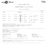
In #978, the transformer with dual primaries also has an electrostatic shield between the primaries and the secondaries. The shield is connected to a purple wire.
The transformer with a single primary, appears not to have a wire connected to an electrostatic shield.
Thanks Mark. This is the kind of detail I'm interested in... So obviously the shielding is good...? Does that translate into a potentially auditory experience? The Antek I bought for my F5 build did not have that shielding. AN-5218.
Last edited:
Just for fun, in case there is something to a "perfect-er transformer"—you peeps that know the science need to tell me... I'm just following my instincts—I have requested a revised quote from Toroid to include dual primaries and the secondary/primary shielding—I was honest with them that the only way to justify it would be to get a group buy going. They are good people and are willing to play the game:
From Toroid:
"I understand. We are one of the best toroidal transformers in the world. We make very quiet transformers for audio amplifiers.
I hope you can find a group of people willing to pay extra to get good quality transformer for their amplifiers."
Okay!
From Toroid:
"I understand. We are one of the best toroidal transformers in the world. We make very quiet transformers for audio amplifiers.
I hope you can find a group of people willing to pay extra to get good quality transformer for their amplifiers."
Okay!
Thanks guys for your answers 🙂
I was referring to the BOM I found when I bought the PCB from the shop:
https://cdn.shopify.com/s/files/1/1006/5046/files/P-PSU-1V30-bom.xls?15967766640867126881
D1-D8, R1-R8, RS1-2,CX1-2, CS1-2 all have ranges or "see notes".
My transfo is a Noratel 360VA, 230V to 2x18V. I googled "Quasimodo thread Noratel" but didnt get anything!
I will spend more time on the forum for my other questions. I'm not used to it yet and dont find it easy to find what you want 🙂
Thanks again!
You'd need to be specific about which parts. I got lost a bit too, and I'd certainly be willing to show you exactly what I used in certain places. Most of it is pretty straight forward with the exception of the snubbers. Someone was kind enough to give me the recommended values for my transformers. I finally understand what they do, but I had to read quite a bit about ringing... what it is, why it happens... what can cause it... etc... The link is likely to the Quasimodo thread. If your exact transformer is listed, then you can use the values in the spreadsheet. If no one has measured your exact transformer, then my personal opinion is that in your situation it will work just fine without an input or output snubber. You can add it later if you choose.
I was referring to the BOM I found when I bought the PCB from the shop:
https://cdn.shopify.com/s/files/1/1006/5046/files/P-PSU-1V30-bom.xls?15967766640867126881
D1-D8, R1-R8, RS1-2,CX1-2, CS1-2 all have ranges or "see notes".
My transfo is a Noratel 360VA, 230V to 2x18V. I googled "Quasimodo thread Noratel" but didnt get anything!
I will spend more time on the forum for my other questions. I'm not used to it yet and dont find it easy to find what you want 🙂
Thanks again!
My transfo is a Noratel 360VA, 230V to 2x18V. I googled "Quasimodo thread Noratel" but didnt get anything!
In browser window (or search engine search field) type in (no quotes):
"site: diyaudio.com Quasimodo thread Noratel"
This pops up:
Quasimodo results (ONLY)
The Antek I used and tested myself is in there—my snubbing value was different however.
Thanks guys for your answers 🙂
I was referring to the BOM I found when I bought the PCB from the shop:
https://cdn.shopify.com/s/files/1/1006/5046/files/P-PSU-1V30-bom.xls?15967766640867126881
D1-D8, R1-R8, RS1-2,CX1-2, CS1-2 all have ranges or "see notes".
My transfo is a Noratel 360VA, 230V to 2x18V. I googled "Quasimodo thread Noratel" but didnt get anything!
I will spend more time on the forum for my other questions. I'm not used to it yet and dont find it easy to find what you want 🙂
Thanks again!
D1 - D8: The BoM provides two options not a range. There are more, but you can pick either of the ones mentioned. Look up the parts from your favorite store. Try to understand the sizes and any meaningful specs. If that's frustrating, just pick one of the two. FWIW, I used the FEP30DPs. Read up and see what other things you'd need to assemble them. I also ordered a set of the monolithic rectifiers mentioned in the thread. I chose not to use them, but I'd advise reading up. Depending on the case you chose, the size of the PSU boards can maybe be a factor. Cost may also be a consideration. Your skill level and/or level of confidence may also come into play.
R1-R8 - As I mentioned, if it has a range, just pick anything within that range. Or read the thread (the very first posts even) and see what the gentleman that created the guide used. It's easy to see in the pictures, and they're mentioned quite a number of times in the thread.
re: snubbers. You've been given advice, and I posted a direct link to the thread with the values up the thread. If you Google as pfarrell advised or click the link I posted and read / search the thread, you're good to go.
If you do a Google search for (I think) "F5 build guide", some kind person created an entire .pdf with more of an instruction sheet format. It also covers the PSU. I downloaded and read it even though I was building a different amp at the time. The information was very helpful.
Have fun!
If you do a Google search for (I think) "F5 build guide", some kind person created an entire .pdf with more of an instruction sheet format. It also covers the PSU. I downloaded and read it even though I was building a different amp at the time. The information was very helpful.
This is actually really good—his wiring is REALLY nice—imo. And he uses the bridge rectifier parts of the PSU board but uses the chassis bottom as a heat sink and splits everything apart for space. Really nice job. Be careful though—I completely forgot that it was for the V2 version of the board... gets super confusing if you try to start biasing on the wrong resistors using his instructions. Ha!
diyAudio F5 Build Guide
"Old V2 build guide"...
Some part seems to have lost its mojo
It’s been since the start of this thread that I’ve had my power supply board up and running in an Aleph J... but now the transformer is... not humming, it’s pulsing, softly perhaps four times a second. For a time it was dimming the LEDs on the board, one side only. It does not always exhibit this behavior.
I Can hear it when I’m close but the amp ran ok. It’s a mechanical sound definitely coming from the transformer. Do I suspect the transformer itself or some other aspect of the amp?
Everything was built right, what might fail that would cause pulsing?
6L6,
I Measured bias across R18 per Aleph J build instruction....0.45 volts dc on the right channel and 0.47 on the left.
I had an issue with a very different tube amp that had LED lights, Christmas lights in fact, that were run off the incoming household voltage. They dimmed/flashed at about the same rate: 4/s and messed with the music presentation until I swapped them out for better bulbs... could the LEDs on the boards have any strange effect? I used some cheap blue LEDs both on the Aleph J boards and on the PSU boards...
Good idea Exteme-Boky but it is only effecting one of many amplifiers I use.
I’m not sure how DC saturation would effect an amp. This has an audible effect, not through the speakers but sitting there on the bench only attached to the household supply.
I’m not sure how DC saturation would effect an amp. This has an audible effect, not through the speakers but sitting there on the bench only attached to the household supply.
With my problem of the 4 cps noise coming from the transformer, seeing as the amp worked fine for five or six years, the question must become in my mind what things wear out?
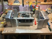
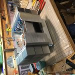
The phots only show the general construction. The PSU is central. I did attach the diodes to the frame for heat dissipation, no wires became crossed/touched there. All solder joints are in good shape and all barrier strips were possessed of good contact. There is no corrosion.
I’ve not gotten down to the actual transformer yet. Is there a way to test it to reveal any anomalies?
I’m about to just rebuild the thing with new better LEDs as that is the only hunch I’ve got to work with. Along those lines, does anyone have a recommendation?
Cheers,
Attachments
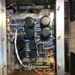
Ok, tearing down further I find one suspect connection, from the transformer to AC2B. I’ll get back to this forum when I’ve reconstructed the amp. More organization this time and no Euro connectors. They seem to loosen up with time and temperature shifts...
Well.... your power supply wiring is waaay toooo long. The whole current path:
transformer - power supply - amplifier - speakers wiring should use as thick as practically possible and as short as possible wiring (bus bars even...).
Check the ACA wiring, especially DC bus from the SMPS to either PCB.
transformer - power supply - amplifier - speakers wiring should use as thick as practically possible and as short as possible wiring (bus bars even...).
Check the ACA wiring, especially DC bus from the SMPS to either PCB.
Attachments
Your concerns are appropriate. There are unique problems when building vertically, some leads must reach across and up, that’s unusual.
It’s not the cause of my issue, I’d like to make clear, my suspicion lies with my choice of connector. Solder would be best but sometimes one must consider the build and tear down sequence. In those cases where a barrier strip is called for I’d recommend standard screw down barrier strip with good copper spades.
The Aleph J was my first SS/Nelson Pass build. I built the case and heat sinks from scrap. I could not afford a pretty premade box, spent all my coin on the other parts. I recommend this approach for creative minds only. I just no longer recommend or use those white plastic “Euro” barrier strips. They have fail me too many times. In theory they are better, in practice, they are not!
For those who wonder about sonic issues with the connection type or any extra inches of wire... don’t worry. It is the wire path more than the amount of wire that matters. (It’s the circuit design that matters most of all!). I’ve not heard any difference between a good solder joint and a good compression joint but I admit one needs to revisit compression joints 10 years down the road while a properly made and cleaned solder joint will last a very long time before needing cleaning. But they do age, and they do require cleaning... and most of the refurbishing work I do finds poorly made solder joint far more difficult to fix than any spade connection. And I’ve seen many a poor solder joint! Most have never been properly cleaned after being made. Flux is nasty and does your circuit no good.
It seems strange for someone asking for diagnostic assistance ranting about build technique I’m sure! I come at this from an artist/craftsman’s perspective, from soldering jewelry to soldering components. Friends asked me to look over old gear and a made a new friend who was a military radio man from the days when radio was king. I’ve also been a technical illustrator for service manuals so I’m keen on being able to access and service anything. I’ve no comrades in this path I’ve taken into the world of HiFi. I very much appreciate all the help I’ve received on this forum. I’m trying to pay it forward.
Cheers!
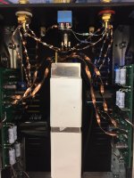
Ok, I’ve fixed the wiring. It was in fact the problem... not a failed component! Everything works fine and the new wire paths are an improvement. Five SS amps and six tube amps from scratch have me finding better solutions even if many would scoff... but hey, what’s the point of building for yourself if you are not going to explore your own abilities and style?
Cheers!
Cheers!
Attachments


- Home
- Amplifiers
- Power Supplies
- diyAudio Power Supply Circuit Board v3 illustrated build guide