I wasn't suggesting to overspec the power supply, just a proper one, but he's got an 800VA transformer in the package deal for a 150W x 2 amp which is much more than required. A wimpy power supply won't give the same punch even at lower volumes though. This isn't a new observation by any means.
I haven't looked into the reason higher voltage makes tweeters more lively but I always assumed it was simply because it's easier to overcome the resistance of the output stage, speaker wiring, ect. I can hear the difference even with my damaged hearing, again not a new observation.
It doesn't matter how good the amplifier design is, if there isn't enough power there to feed it it's not going to perform properly. Crap in, crap out... A prime example is 99% of the home theater receivers in use today.
Sanken 2sa1668/2sc4382 https://www.semicon.sanken-ele.co.jp/sk_content/2sa1667_ds_en.pdf are the recommended drivers.
With a whole sanken EF2 , HB current "droop" would be less thanthe ON equivalent . You could even run the HB VAS at lower Ic for a "green" /cool HB.
Greetings programs!
Big shoutout to OS, wherever he is, for sharing this circuit. I'm looking forward to building your other designs once this HB is singing. HUGE thanks to all whom have shared your knowledge and experience on these forums!
Long time lurker, first time poster here. HB is my first amp build.
I have purchased the 2sa1668/2sc4382 drivers and 2sa2151/2sc6011 output devices per the post above. Is there any benefit to running lower VAS Ic other than temperature and power consumption? Any harm in not lowering VAS Ic other than increased heat? If relevant, LTP is ZTX1051a. Other transistors are 1845/992 and 3503/1381. Antek AN-8435 with 48000uF/rail for 4ohm.
Grateful for any input/advise you may have!
dNr
Getting my feet wet with a Honey Badger
Hi All. I’ve been reading up on building a Honey Badger for several weeks now and am a bit confused concerning the power rating of this amp. The build guide says that the amp can handle 4ohm speakers (150W @ 8 ohms or 250W @ 4 ohms) presumably with a 45v 800VA transformer (recommended in the build guide);
But the I also ran across this bit of info that seems to contradict this;
I’m hoping to build a dual mono amp with around 150watts that will easily drive inefficient 6ohm speakers, but also won’t mind 4ohm, just for flexibility. Which direction should I go concerning transformers and PSU? Also, given your advice on transformer, will I need to deviate any from the other suggested components in the guide?
Also, the build guide on diyaudiostore.com looks a bit dated. Is the a better build guide somewhere or is the dated guide still relevant?
Thanks!
PS - I’m a first time builder with limited beginner knowledge of electronics.
Hi All. I’ve been reading up on building a Honey Badger for several weeks now and am a bit confused concerning the power rating of this amp. The build guide says that the amp can handle 4ohm speakers (150W @ 8 ohms or 250W @ 4 ohms) presumably with a 45v 800VA transformer (recommended in the build guide);
Driving low impedance loads is not a problem with this amp and with an estimated output power of about 150W on an 8 ohms load, this amp has plenty to give and the headroom you’ve always wished for. The circuit is very stable and well behaved, and the circuit design is both innovative and formidable.
Basic design goals were:
• An output power of about 150W @ 8 ohms (~250W @ 4 ohms)
• 3 pairs of easily obtained BJT output devices in TO-3P or TO-247 packages
• An “all in one” construction approach whereby the builder need only apply a clean power supply and the amp is ready to go
But the I also ran across this bit of info that seems to contradict this;
30+30Vac gives ~ +-42Vdc & ~ 70 to 80W into 8r0 and suits 4ohms speaker
35+35Vac gives ~ +-50Vdc & ~ 100 to 110W into 8r0 and suits 4ohm speaker
40+40Vac gives ~ +-59Vdc & ~ 140 to 160W into 8r0 and possibly suits 6ohms speaker
45+45Vac gives ~ +-68Vdc & ~ 190 to 210W into 8r0, does not suit lower impedance speaker.
The smoothing cap voltage ratings are
>=63Vdc suit 30Vac & 35Vac
>=80Vdc suits 45Vac
63Vdc may suit 40Vac but must be checked for actual worst case voltage for your transformer and mains supply.
My 230:40+40Vac transformer fed with 240Vac gives ~ +-58.5Vdc on the smoothing caps with single bridge rectifiers, but 254Vac takes the smoothing caps to just below their safe and guaranteed limit of 63Vac if the rail fuses have blown, i.e zero quiescent current.
I’m hoping to build a dual mono amp with around 150watts that will easily drive inefficient 6ohm speakers, but also won’t mind 4ohm, just for flexibility. Which direction should I go concerning transformers and PSU? Also, given your advice on transformer, will I need to deviate any from the other suggested components in the guide?
Also, the build guide on diyaudiostore.com looks a bit dated. Is the a better build guide somewhere or is the dated guide still relevant?
Thanks!
PS - I’m a first time builder with limited beginner knowledge of electronics.
Hi guys, if you have ever wondered how these amplifiers actually work and would like to watch a few educational videos which may help you design your own one day. Check out this channel on YouTube SW Audio YouTube Channel
YouTube
Don't forget to like and subscribe.
And this DIY Audio thread.
SW-VFA-01: Audio power amplifier video series
YouTube
Don't forget to like and subscribe.
And this DIY Audio thread.
SW-VFA-01: Audio power amplifier video series
Last edited:
Thanks for sharing that channel. The information shared is very helpful, even if a bit over my head. Now I’m contemplating whether I should wait to build the VFA-01. Honey Badger seems like an awesome amp as it sits today, so if this proves to be even marginally better, then man... can’t wait to try it. I would love to own a Mcintosh MC152, so I love that Sandro is baselining his build on it and the Honey Badger. Got to love diyaudio community.Hi guys, if you have ever wondered how these amplifiers actually work and would like to watch a few educational videos which may help you design your own one day. Check out this channel on YouTube SW Audio YouTube Channel
YouTube
Don't forget to like and subscribe.
And this DIY Audio thread.
SW-VFA-01: Audio power amplifier video series
Considering building this amplifier and I know I saw a list of alternative parts somewhere on this forum but cannot find it now. Given how fast electronic parts become obsolete many parts are obsolete in the diyaudio store BOM. I hope someone knows where to find the alternative active parts list.
Just want to say thank you!
New here. I subscribed.
I want to say a big thank you and keep up the good work.
I've always wanted to now how those amplifiers how designed.
You are helping me short circuit the process!
Hi guys, if you have ever wondered how these amplifiers actually work and would like to watch a few educational videos which may help you design your own one day. Check out this channel on YouTube SW Audio YouTube Channel
YouTube
Don't forget to like and subscribe.
And this DIY Audio thread.
SW-VFA-01: Audio power amplifier video series
New here. I subscribed.
I want to say a big thank you and keep up the good work.
I've always wanted to now how those amplifiers how designed.
You are helping me short circuit the process!
I am considering this build, but it sure would be nice if the BOM was for board V2.4 same with schematics. There doesn't seem to be a clear path here fellas...
JT
JT
Know one is maintaining the BOM obviously. But it is a generic design where many common passive components will do the job. Just make sure you use the semis called for. I’d have to look at it again, it has been years, Going from memory ksa992, ksc1845, vas ksa1381 ,ksc3503
Use mje15032,33 drivers and onsemi output stage mjl1302,1381 etc
Use mje15032,33 drivers and onsemi output stage mjl1302,1381 etc
If it's going to be in the DIY store, IMHO it should be maintained at least for board versions and current schematic, or it should be removed from the store....
rs, if you would be so kind that would be nice, kinda wishing I hadn't ordered the boards right about now.
I mean the BOM is for V2 the Schematic is for version 2.2. There is a picture of a schematic for version 2.4, but it is blurry and hard to read.
rs, if you would be so kind that would be nice, kinda wishing I hadn't ordered the boards right about now.
I mean the BOM is for V2 the Schematic is for version 2.2. There is a picture of a schematic for version 2.4, but it is blurry and hard to read.
Last edited:
I see the HB BOM on the help desk thread. I guess that is where you are to ask questions. But a link to a shopping cart would make life so much easier for builders. This is what I do for the designs I sell.
There is no problem building te v2.4 with the V2.2 schematic and V2 BOM. but you may want to use the BOM in the buildguide instead.
But you do need to check the lead diameter of the small resistors are no more then 0.55mm.
But you do need to check the lead diameter of the small resistors are no more then 0.55mm.
Last edited:
THanks
Thanks AS, I did see where I think it was you who had some resistors you wanted to use, but they would not fit because of the narrow holes. There was discussion of milling the legs down. 😛
Thanks for your input... has anyone built the V2.4 out there? Any thoughts are welcome.
Thanks
JT
Thanks AS, I did see where I think it was you who had some resistors you wanted to use, but they would not fit because of the narrow holes. There was discussion of milling the legs down. 😛
Thanks for your input... has anyone built the V2.4 out there? Any thoughts are welcome.
Thanks
JT
That was not me. i knew about that before i ordered any parts 🙂 I think i answered somone who wanted to use dale 55's resistors.
I've build a 5ch of the V2.4. With nothing more then schematics and BOM and the guide from the store. The C2 270pF is a little pain to get a hold of.
I've build a 5ch of the V2.4. With nothing more then schematics and BOM and the guide from the store. The C2 270pF is a little pain to get a hold of.
Attachments
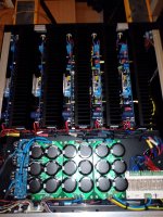
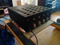
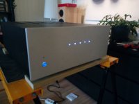
I saw your amplifier... lovely build that. You built it with minimal input alas, I am not you Lord AudioSan. 🙂
I bet the lights dim when you turn that monster on heheh.
I bet the lights dim when you turn that monster on heheh.
Tnx 🙂 The lights stays bright 🙂
There is a lot of bright minds here that will guide you on your jurney
There is a lot of bright minds here that will guide you on your jurney
Hello Friends,
I am planning to make the Honey Badger. I could not find the version 2.4 layout here for the toner transfer method. Have seen the below Sprint file posted by Still4given. My question is, Is this a tested and working layout?. Please let me know if any one of you have already tried it.
Thanks
Sha
I am planning to make the Honey Badger. I could not find the version 2.4 layout here for the toner transfer method. Have seen the below Sprint file posted by Still4given. My question is, Is this a tested and working layout?. Please let me know if any one of you have already tried it.
Thanks
Sha
Hello Everyone,
I'm just starting this project, but firstly I simulate it. I have question about current source on the IPS. Could you explain why current on R14 is 3.75 mA? Is there any forum/video which explain in detail honey badger amplifier?
Thank you
Jérôme
I'm just starting this project, but firstly I simulate it. I have question about current source on the IPS. Could you explain why current on R14 is 3.75 mA? Is there any forum/video which explain in detail honey badger amplifier?
Thank you
Jérôme
- Home
- Amplifiers
- Solid State
- diyAB Amp - The "Honey Badger"