This example was build only to how to select values of resistors and calculate your circuit ... I dont know for you setup what value you should select ... your are building your own set up .. maybe maximum power .. or current .. you should optimize according to your speaker ...??
This example was build only to how to select values of resistors and calculate your circuit ... I dont know for you setup what value you should select ... your are building your own set up .. maybe maximum power .. or current .. you should optimize according to your speaker ...??
Thanks,
OK, so you have chosen 4A per device as an example only, not related to a typical two channel HB built by the majority here.
On second thought 4A may be appropriate as Vmax and I max do not go together. I have to check how I changes with V.
Limiting current in each transistor is probably a better approach than controlling the overall output as current (power dissipation) sharing among transistors may not be even enough.
cheers,
Last edited:
using one protection transistor for a group of 3 output is usual and will work if thermal tracking is good ( all transistors on one single heatsink and with similar heat transfer device )
You dont need 3 separate protection circuit.
You dont need 3 separate protection circuit.
I meant output transistors as in this circuit their currents are independently checked. The first one to get 4A will trigger this protection circuit. As I have Re=0.18 ohm voltage drop across it at 4A is only 0.72V. As original HB did not have current limiter I used smaller Re, which lowers distortion. SS9014 has Vbe (on) =0.63V at Ic=2mA, at 3.2mA it'll be about 0.65V. Luckily I did not go for Re=0.1 - 0.12ohm as I would have ended with negative voltage drops across R5-R6 (1k resistors).
cheers,
cheers,
Last edited:
Try fo figure out what will happend if you omit R8 - R7 ..voltage at the base of T4 will be the mean voltage from R1- R2- R3 ... then it will react to mean current ... same thing will happen with R8 - R7 in place ... protection will work according to mean current.
@janusz
MJL21193/MJL21194 triplicate, and in this case, if the transformer is not more than 550VA, then there is not more in than out. That may help durability. Also, highly linear.
MJL21193/MJL21194 triplicate, and in this case, if the transformer is not more than 550VA, then there is not more in than out. That may help durability. Also, highly linear.
I'm using SemeLabs MG6331/9411s, which have somewhat better SOA figures and much wider bandwidth than MJL2119x.
Toroid is 500VA 2x45V nominal. There will be two dual module amps. So eg one module of the Left channel amp will cover 80Hz to about 600-750Hz and the other one above that. I find it to be a good compromise between a fully active system and a passive one.
cheers,
Toroid is 500VA 2x45V nominal. There will be two dual module amps. So eg one module of the Left channel amp will cover 80Hz to about 600-750Hz and the other one above that. I find it to be a good compromise between a fully active system and a passive one.
cheers,
A finer device indeed. However, 60mhz could possibly take somewhat more compensation efforts. I do not know.
I assume you don't mean milli-Hertz.............However, 60mhz could possibly take somewhat more compensation efforts...............
Did you mean 60MHz, (Mega-Hertz)
Yes sir.Did you mean 60MHz, (Mega-Hertz)
And, some observations on the topic:
The cost of extreme speed is that it won't be placid without extra effort, which usually involves compensation to reduce the fast transistors to a more placid speed. This is not the same as using slower devices because. . . The benefit of extreme speed has nothing to do with the speed but rather the lower parasitic capacitance and thereby less noise. MG6331 has 250pF, parasitic capacitance--a low noise output device.
However, this amplifier has parallel outputs with ballast resistors, so, in theory if we'd have used the much less nervous MJL21194's 4~6 MHz, then the 500pF, parasitic capacitance noises should get caught in the ballast resistors, not the speaker. Therefore, the MJL21194's device capacitance in this case does nothing other than make the amplifier somewhat more stable and thereby more durable as well--perhaps somewhat less likely to go up in smoke during a minor TMC glitch.
When comparing the datasheets: I'm a bit suspicious of simultaneously half the capacitance yet also more current handling, which are factors in conflict with real transistors. Assuming the speed and capacitance is true, then when I calculate without the MG6331's datasheet current figures, I get 140W for triplicate MG6331/9411, and if the transformer is greater than 220VA, the amplifier is fuse reliant, and Honey Badger's fuse values might be too large. So, for the MG6331/9411, I'd think that we should probably increase/customize compensation and lower the fuse values a bit.
So, did I analyze that right?
Dependance on fuses, assuming that they are not faulty, is rather tricky unless one goes sufficiently down along their current specs. But then they would often blow at high signal levels so practically it's much better to add a current limiter such as that presented by audiofan or some other design. Alternatively, one could design outputs based on lateral mosfets but apparently Exicons or BUZs are not as robust as old Hitachis.
cheers,
cheers,
Well, that is all true. I had an lm1875 project for several years that blew up fairly often due to million VA sort of transformer error, when the max was 36.
HB with VAS triplet like in Volverine
Attached is HB circuit diagram with VAS triplet like in volverine and separated sources. Simulation works fine. I do not know what improvemenet it would give in practice as simulation and reality is not exactly the same thing. A lot also depends how well written are used transistor models etc. EG I have two models of the same transistors (2sa1940/sc5171) and under simulation one show 5 times lower distortion that the other.
cheers,
PS ostripper, could you please explain what benefits triplet VAS would bring in reality?
Attachments
Attached is HB circuit diagram with VAS triplet like in volverine and separated sources. Simulation works fine. I do not know what improvemenet it would give in practice as simulation and reality is not exactly the same thing. A lot also depends how well written are used transistor models etc. EG I have two models of the same transistors (2sa1940/sc5171) and under simulation one show 5 times lower distortion that the other.
cheers,
PS ostripper, could you please explain what benefits triplet VAS would bring in reality?
Advantages -
- less VAS current , far less load on VAS. could be run w/ no VAS heatsink.
Output load has no effect on VAS / w EF3. THD is less than w/EF2.
Disadvantages - needs slightly more rail V (3 Vbe drops - EF3) ... more
complicated.
In light of this , and using standard OEM speakers ..... The Badger/
wolverine differences would be hard to discern. I offered the Wolverine
as just another option for a input stage/VAS to compare to the
current feedback offerings.
Badger = textbook / better than OEM , easy + well documented.
10ppm vs. 5ppm would be nearly inaudible.
PS - I use the different/better ? CCS + the same BAVxx clamp diode
(on the wolverine) ,
this would amount to only an academic improvement. Only a
totally different topology would amount to any change in "character" ?
Thanks ostripper,
My LT spice does not show any differences in distortion levels between HB and this modified one. Anyway, I do not think there is any chance of hearing 10ppm - 5ppm difference. In more distant past we did tests and even professional and sufficiently young musicians could not tell apart amplifiers even with larger differences in distortion levels. No problem with speakers, these may differ a lot. There was no problem hearing difference between mosfets (lateral) and bjts but in those times bjt outputs were nothing to brag about.
What CCS do you use?
Thanks,
cheers,
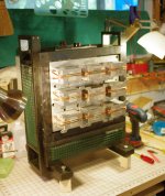
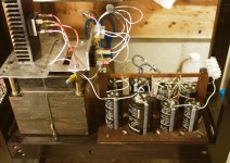
One more HB in service
'Just finished a day listening to my junkyard HB. Wow 🙂. It is muscular with a huge and articulate sound stage!
Now it's not much to look at but that's OK. I made it from largely recycled parts. Not much cost at all for this build 🙂))
The heat sinks are from old computers and you can see my heat spreader though a stout 1/2 inch thick, is full of random holes. The transformer is from an old Crown DC300A as well as a pair of large caps, the bridge rectifier and a few other select caps.
The PSU is a Nelson Pass formula, it performs flawlessly. And due to the tall and open design the junk yard HB never goes above 8 degrees F above ambient (bias is at 40mA TP1 to TP2...)
I put this out there for anyone on an extremely tight budget; it can be done!
Attachments


- Home
- Amplifiers
- Solid State
- diyAB Amp - The "Honey Badger"