Would I need to alter resisters since gain different?😕
no need...
MPSA06 is also backordered
ZTX450 is available but has a Vceo of only 45V. Problematic for Q7/8 with 60V rails.
Is looks like AmpsLab has KSC1845 available in lots of 20.
unlike the VAS and output stage trannies, Q7/8 does not swing voltage, it is constant current, i see no reason for concern....
ZTX450 for Q8 is more than plenty....Nelson Pass's favorite.....
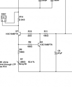
for Q7, MPSA06 is more than enough even if you use a rail voltage higher than 60volts, you can even increase the value of R14 from 2k to 10k, the output impedance of the ring of two being around 200k is even helped by the higher value of R14...
btw, the usual caveat, be mindful of the pinouts...
Attachments
Last edited:
$40 minimum order
Amplabs has $40 minimum which is steep for 8 transistors. Are these substitutes also good for Q3,Q4?
MPSA06 is also backordered
ZTX450 is available but has a Vceo of only 45V. Problematic for Q7/8 with 60V rails.
Is looks like AmpsLab has KSC1845 available in lots of 20.
Amplabs has $40 minimum which is steep for 8 transistors. Are these substitutes also good for Q3,Q4?
I just ordered some - total of $23 with shipping. They shipped out the next day. Still not cheap, but beats waiting 6+ months.
Amplabs has $40 minimum which is steep for 8 transistors. Are these substitutes also good for Q3,Q4?
mpsa06 should work fine in that spot, be mindfull of the pinouts...
Digikey shipped KSA1845
Web site states O available but I just got e-mail that they shipped me my order including the KSA1845.
Thank you all for looking into this, you are the best
Web site states O available but I just got e-mail that they shipped me my order including the KSA1845.
Thank you all for looking into this, you are the best
yes part ksc1845
my typing is almost as good as my ability to solder surface mount chips, yes part KSC1845. $2.04 for 10 of them plus $0.20 tariff shipped from Digikey. I live very close to Thief River Falls so should get tomorrow unless weather delays due to extreme cold (-26F, wind chill -50F)
my typing is almost as good as my ability to solder surface mount chips, yes part KSC1845. $2.04 for 10 of them plus $0.20 tariff shipped from Digikey. I live very close to Thief River Falls so should get tomorrow unless weather delays due to extreme cold (-26F, wind chill -50F)
Last edited:
Can't start build
I finally got parts that had been backordered for a couple of months and was pretty exited to get started on construction. I'm greater than $700 invested if look at Deluxe 4 case, transformer, and parts I ordered. I had a whole weekend to work on it. Then, I found not a single resistor leg would fit. They should emphasize that the through hole openings are not just tight they are unnecessarily pinhole tight about 1/2 the width of a 1/4 watt dale resistor leg. Why are they so tight? There appears to be plenty of room for larger openings as the solder pads are very generous. Pretty sure I am not going to bother to finish this now as I am just too frustrated. I would like someone to add to parts list that one should order flimsy, cheap parts on purpose.
I finally got parts that had been backordered for a couple of months and was pretty exited to get started on construction. I'm greater than $700 invested if look at Deluxe 4 case, transformer, and parts I ordered. I had a whole weekend to work on it. Then, I found not a single resistor leg would fit. They should emphasize that the through hole openings are not just tight they are unnecessarily pinhole tight about 1/2 the width of a 1/4 watt dale resistor leg. Why are they so tight? There appears to be plenty of room for larger openings as the solder pads are very generous. Pretty sure I am not going to bother to finish this now as I am just too frustrated. I would like someone to add to parts list that one should order flimsy, cheap parts on purpose.
Looks like the resistor leads in the published BOM are all 0.44mm diameter whereas the Dale CMF55s (1/2 watt) are 0.64mm diameter. Assuming that's what you are using, though you said 1/4 watt. The 1/4 watt Dale CMF50s are 0.41mm lead diameter, so those would fit in theory.
Unless there's a manufacturing issue with the boards you received.
Unless there's a manufacturing issue with the boards you received.
Hey Jim! Argh. That sucks.
A few people over the years have had the same problem. The holes are exactly as specified by the gerber files we received from the designer, OSTripper. I will confirm the exact sizing on the PCB holes and post a note on the sales page and BOM.
As to how to resolve this for you...
The designer Pete (OSTripper) has been uncontactable for many years. However I have sent him an email just now to see if he responds. If I can get in touch with him, we can get the original design files and easily increase the size of the holes (we never received the design files from him, just the raw gerber files).
What I can suggest is that we produce a new batch of boards with increased hole size, and I send you a free replacement. This will take a few months, but if you are happy to wait I am happy to do this. I will try to get the original files from Pete, and if that isn't a viable option, I will have the holes in the original gerber files manually resized, and then make, ship, and stock the new batch, and send you a set.
What is the ideal new size for the resistor (and other) holes?
Jason, there are a lot of board layout designers here, a raw gerber files can be modified i believe....
a bigger thru hole will make repairs easier imho....from building two pairs of your boards...
the honey badger thread has a lot of inputs if you can read them...
a bigger thru hole will make repairs easier imho....from building two pairs of your boards...
the honey badger thread has a lot of inputs if you can read them...
Looks like the resistor leads in the published BOM are all 0.44mm diameter whereas the Dale CMF55s (1/2 watt) are 0.64mm diameter. Assuming that's what you are using, though you said 1/4 watt. The 1/4 watt Dale CMF50s are 0.41mm lead diameter, so those would fit in theory.
Unless there's a manufacturing issue with the boards you received.
thankfully the pad circles are big enough so that you can still solder in resistors although i admit that is not ideal...
I have never seen anyone on this forum complains about the resistor holes size on any FirstWatt amp PCB.
Why the hole size cannot be made as same as all other amp boards.
I heard an very interest story already on another hifi forum that claims the hole size on The "Honey Badger" was purposefully made very tight. The leads can make contact with gold to avoid "the alloy sound" caused by the solder. That's why The "Honey Badger" sounds so beautifully.
we are not into that kind here.... 😀
such types of comments never fail to amaze me, but i am never swayed, i just stay away and focus on how the thing really works...
such types of comments never fail to amaze me, but i am never swayed, i just stay away and focus on how the thing really works...
Hi Guys, I have been tweaking my HB over the past few months and have managed to reduce the distortion considerably since my first measurement.
I recently found that increasing the ltp current to 6mA and then changing the LTP degeneration resistors to 120 ohms and changing C7 to 82pf and C8 to 390p to achieve the same unity gain crossover frequency FC. Doing so reduce my 2nd harmonic distortion from -80dB to -90dB and my 4th harmonic from -90dB to -95dB.
First picture is one of my first measurements.
Second is the measurement immediately before the 6mA change.
Last photo is after the 6mA change
Hi Guys, I have been tweaking my HB over the past few months and have managed to reduce the distortion considerably since my first measurement.
I recently found that increasing the ltp current to 6mA and then changing the LTP degeneration resistors to 120 ohms and changing C7 to 82pf and C8 to 390p to achieve the same unity gain crossover frequency FC. Doing so reduce my 2nd harmonic distortion from -80dB to -90dB and my 4th harmonic from -90dB to -95dB.
First picture is one of my first measurements.
Second is the measurement immediately before the 6mA change.
Last photo is after the 6mA change View attachment 924507View attachment 924508View attachment 924509
Keeo it up bro... we are watching. 😉
- Home
- Amplifiers
- Solid State
- diyAB Amp - The "Honey Badger"