Fuses have no resistance.I would think a resisitor, of any wattage, would have a much longer "blowing" time than a fuse. But hey, I'm not an expert. I'll stick with only fast blow fuses on my rails. Of course, even a fast blow fuse may not protect the outputs depending on the circuit, the device and the circumstance creating the short.
Without resistance there is no voltage drop.No voltage drop no protection. 😉
Here's a quick stripped down version of how the input stage of amplifier operates. Hopefully this will make thing a little easier to comprehend.
The input stage is a current amplifier. Q1 and Q2 make up what is called a LTP (long tailed pair) input stage. There is a constant current source (Q7 and Q8) that keeps a constant current for the LTP to share. As input signal voltage rises, more current flows through Q1 causing it to steal current from Q2. Feedback from the output stage turns on Q2 which make it steal most of the current back from Q1. This is how the the amount of amplification is controlled in the amplifier. R20 and R21 are load resistors (ignore Q4, Q5, Q6 and Q7 for now). The current through the input stage causes a voltage drop through the load resistors. This voltage drop will increase and decrease with the input signal that is fed into Q1, and will be corrected by the feedback signal that is returned to Q2. The current we see across the load resistors will mimic the input signal, but will be fluctuating at a much higher current "swing".
R7 adjusts the constant current source for the input stage. The amount of current flowing through the load resistors effects how much voltage will "swing" with the input signal. If there's not enough current available Q1 will switch fully on and/or off with the higher or lower peaks of the input signal. This is called clipping and sounds terrible. If the current is too high the input stage will overheat, among other problems. The voltage drop from the load resistor for Q1 is the signal that is passed on the the rest of the amplifier.
You need to adjust R7 so the input stage has 3.75mA flowing through it. That's the sweet spot that the input stage has been tuned to operate at. To measure the input stage current you need to measure the voltage drop across R14 and set it to 8.25V.
Q1 and Q2 won't be a perfectly matched pair so Q2 can't perfectly correct what is coming out of the input stage. R17 is added to force Q2 to properly correct the signal. Q2 is working correctly when the DC offset of the output stage is at 0V

If you are running fast blow fuses on the rails it might be a good idea to have a really close look at the center on the fuse element for any sign of discolouration. They can actually start to melt on higher output swings of the amplifier and cause what is called "fuse distortion" (looks similar to clipping on a scope). Often you can use a lower rated slow blow fuse on the rails which can actually offer a little more protection in some cases.I would think a resisitor, of any wattage, would have a much longer "blowing" time than a fuse. But hey, I'm not an expert. I'll stick with only fast blow fuses on my rails. Of course, even a fast blow fuse may not protect the outputs depending on the circuit, the device and the circumstance creating the short.
I agree with you completely about removing the resistors that are bypassing the fuses, that's just wrong! So is placing the fuse on the amplifier board itself. The should be at the source, the supply. As is there's no protection for the supply if wiring is shorted.
Fuses do have resistance and do produce a voltage drop, that's how they work. The voltage drop and resistance are very small, but do climb as the fuse rating get smaller. The resistance of the fuse element also rises as the temperature rises, more current flow will cause the temp to rise and the resistance to go up and the voltage drop to climb. This is why @jwilhelm's statment about fast blow fuses makes a lot of sense.Fuses have no resistance.
Without resistance there is no voltage drop.No voltage drop no protection. 😉
Want to talk to a newbie about the non linearity resistance curve of fuses? Do you encourage anyone to rely on fuses to test an amp? Sorry, but I have a different opinion.☺️
Of course we speak for test conditions only!
After a susses full test resistors should be replaced by fuses!
I use resistors 18R/5w in series with the rails & a bulb short circuit protection circuit in the primary side always.
I haven't any burned part anymore.
Of course we speak for test conditions only!
After a susses full test resistors should be replaced by fuses!
I use resistors 18R/5w in series with the rails & a bulb short circuit protection circuit in the primary side always.
I haven't any burned part anymore.
Last edited:
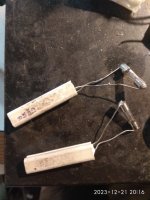
Here is my lifeboat.
Take two blown fuses,solder the resistors and safe test.
You can smell the fault 😤
or sence the hot!
Better way,connect a voltmeter or two across each resistor and read the voltage.
Ohm is your friend.
I=U/R.
For a non fault amplifier you must expect something between 1-2V.
You can try to adjust the bias,not for recommended vslue but just to see the voltage drop varies.Adjust for the minimum voltage reading.
Amplifier INPUT sorted.
If you read higher, disconnect the main immediately and inspect for the reason.
Attachments
Last edited:
Sorry to sound like a broken record but is there an approved/sanctified schematic and current BOM of stuff that is widely available?
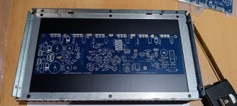
Friends, I have ordered the boards for Wolverine but I'm going to build HB as well. The PCBs on the HB I already have at home are really gorgeous blue+gold. After reading the whole thread, I'll go the way of Stuart, he's done a lot of great work and the BOM will be created from his modified 2.5.4 schematic. I will add an updated BOM by the end of the year. Important thing to keep in mind to avoid oscillations, ...(select input transistors at hfe 300 max and adjust current for zener diode 15K/1W)
Merry Christmas from Slovakia
Merry Christmas from Slovakia
Attachments
I have a theoretical question. Let's assume that I use one of the higher power output BJTs, e.g. MJL4281/MJL4302 and set the rail voltage such that I am within the SOA with a single output pair. Can I, in this case, short the 0R22 emitter resistors or would this cause whatever instabilities? A related technical question is how to measure the bias, then. I think I would just measure the voltage drop on the base resistors of the output transistors and use their hFE value to estimate the collector current.
How much is needed for this purpose? Can it go lower, say 0R1? In case of a single pair OS the emitter resistors are not needed to account for imperfect transistor matching and there are people who argue for better dynamics at lower emitter resistor values.
Emitter resistors are needed whenever there are multiple output devices. 0R1 isn't enough resistance to force the output transistors to balance.
In a high gain amp using lots of feedback you hear the input stage, not the output stage. People can hear the difference between blue and red wire if they want to. It's called the placebo effect and eventually leads to enormous input caps that bring on hum and stands to lift your speaker wires off the floor. It's safer to use common sense and ignore most of these suggestions.
In a high gain amp using lots of feedback you hear the input stage, not the output stage. People can hear the difference between blue and red wire if they want to. It's called the placebo effect and eventually leads to enormous input caps that bring on hum and stands to lift your speaker wires off the floor. It's safer to use common sense and ignore most of these suggestions.
Please read again my post #5170. My theoretical starting point is a single pair output stage.
The Honeybadger is a three output pair amplifier and is laid out accordingly. Why create a solution for something that's not a problem? Audibly there's no advantage to altering this and output power will suffer dramatically.
I agree with you, experimenting is not a must.Why create a solution for something that's not a problem?
There's nothing wrong with experimenting, but if you want to deviate from the original design it's best to start another thread to avoid confusing new builders who come here for advice.
Harmonic profiles of an amplifier are very well worth exploring. Many very good designers have discovered ultra-low distortion levels aren't usually preferred by many listeners. Instead reasonable distortion levels with declining levels of harmonics actually sound better. Again this is subjective.
Harmonic profiles of an amplifier are very well worth exploring. Many very good designers have discovered ultra-low distortion levels aren't usually preferred by many listeners. Instead reasonable distortion levels with declining levels of harmonics actually sound better. Again this is subjective.
Keep the emitter resistors. In conjunction with the thermally coupled bias spreader, they help to stabilize the quiescent current.
Best regards!
Best regards!
Thank you, Kay, I will keep them. I am only uncertain which parts are you referring to under "thermally coupled bias spreader"?
mcsontos - I wrote a thermal simulator to determine the value of emitter resistors in my amplifier. 0.22 ohms requires good thermal tracking. Thermal tracking can be sloppy with 0.47 ohms. Much below 0.22 ohms, thermal runaway becomes unavoidable.
If you want to experiment with blowing up an amplifier, do it in simulation. 😉
Ed
If you want to experiment with blowing up an amplifier, do it in simulation. 😉
Ed
- Home
- Amplifiers
- Solid State
- diyAB Amp The "Honey Badger" build thread