Hello
greetings anybody help me at 55 volt dc supply rails how do i do the biasing
of honey badger how many millivolts on base of output transistors and reading
over emitter resistances maybe someone can help me
warm regards
Andrew
greetings anybody help me at 55 volt dc supply rails how do i do the biasing
of honey badger how many millivolts on base of output transistors and reading
over emitter resistances maybe someone can help me
warm regards
Andrew
The bias isn't dependent on the supply voltage. 20--25mV between emitters is mentioned in the setup guide, assuming 0.22 ohm emitter resistors (50mA per output device).
Hello
greetings anybody help me at 55 volt dc supply rails how do i do the biasing
of honey badger how many millivolts on base of output transistors and reading
over emitter resistances maybe someone can help me
warm regards
Andrew
you do not measure the base voltage, measure the emitter resistor voltage drop instead...as Mark Tillotson said...
Thanks
Thanks Stuart.. I' haven't put it back in the chassis yet, probably tomorrow. I'll do that and then I need to pull off it and get a website up and running. After that, I'll come back and do some testing we were working on.
It occurred to me that I might get much different readings and Indeed still might not get to where you set yours for testing. We have different rail voltages and diff bias, so I don't think a comparison is even possible, or worthwhile.
I'm going to look at my numbers and they will be what they are. We have to many differences in our amps to do what we were thinking. Hell, I'm not even using the same devices you are....
I do thank you for the help in building the attenuation. 😉
Well done. I have been following your progress through this.
Thanks Stuart.. I' haven't put it back in the chassis yet, probably tomorrow. I'll do that and then I need to pull off it and get a website up and running. After that, I'll come back and do some testing we were working on.
It occurred to me that I might get much different readings and Indeed still might not get to where you set yours for testing. We have different rail voltages and diff bias, so I don't think a comparison is even possible, or worthwhile.
I'm going to look at my numbers and they will be what they are. We have to many differences in our amps to do what we were thinking. Hell, I'm not even using the same devices you are....
I do thank you for the help in building the attenuation. 😉
I do thank you for the help in building the attenuation. 😉
No worries, happy to help out. If you can run a test with your amplifier module outside the case and then one in the case and compare. This will show you what influence your internal wiring, power supply loop area etc is having on your measurements.
What load resistor are you using again. Can you post a image?
Settled on a bias of 36mv, it was running about 30mV before. It's running a lot hotter. I ran it up to 100W or so and let it rip for 40mins and the highest temp I found was 46.6C.
Once I put it back in and check numbers everything looked good, so I watched it idle for 10mins or so then streamed Audioslave as loud as I could stand and she never burped. 🙂
Off to build a website, so I won't get back to doing anymore testing for a week or two.
@Stuart I'll get you some numbers after that. As I said though, I'm not going to worry to much about them... the amp sound good. 🙂
Settled on a bias of 36mv, it was running about 30mV before.
I found that the lowest distortion was achieved at 19mV but deteriorated quickly below that. I recommend setting it to around 22mV
Hello
greetings how much is the maximum input sensivity my dac player output signal
2 volt RMS .
warm regards
Andrew
greetings how much is the maximum input sensivity my dac player output signal
2 volt RMS .
warm regards
Andrew
Settled on a bias of 36mv, it was running about 30mV before. It's running a lot hotter. I ran it up to 100W or so and let it rip for 40mins and the highest temp I found was 46.6C.
the objective of biasing is really the elimination of notch or zero crossing distortion, into 1 watt 8 ohm dummy load....
you need to bias your amp so that none of this is seen on the scope...
bias enough to get rid of this, more bias current and your heatsink gets warmer, not really required...
if you have a distortion meter it will be interesting to find how much bias lowered THD.....and by how much idle power increase to bring thd down...
An externally hosted image should be here but it was not working when we last tested it.
below is the correct sine wave looks....
Last edited:
Some numbers for you.Hello
greetings how much is the maximum input sensivity my dac player output signal
2 volt RMS .
warm regards
Andrew
If your max output is 180wrms into a 8 ohm load.
Then your input will be 1.414VRMS
as the closed loop gain is approximately 26.83 Av
Hi Tony,
Great post and a good explanation of bias current. Many people run the bias way higher than it needs to be.
-Chris
Great post and a good explanation of bias current. Many people run the bias way higher than it needs to be.
-Chris
Hi Tony,
Great post and a good explanation of bias current. Many people run the bias way higher than it needs to be.
-Chris
and that is sad....
if you can get away with just enough, why waste power?
and the honeybadger is such a fine amp by Ostriper, you do not need ppm thd to enjoy this amp...
Hi Tony,
Well, exactly! My SymAsym only needs 5 mA bias to reach a distortion null and kill crossover distortion. However I have seen amplifiers that needed 250 mA to get rid of crossover notches. Now that is sad.
Well, exactly! My SymAsym only needs 5 mA bias to reach a distortion null and kill crossover distortion. However I have seen amplifiers that needed 250 mA to get rid of crossover notches. Now that is sad.
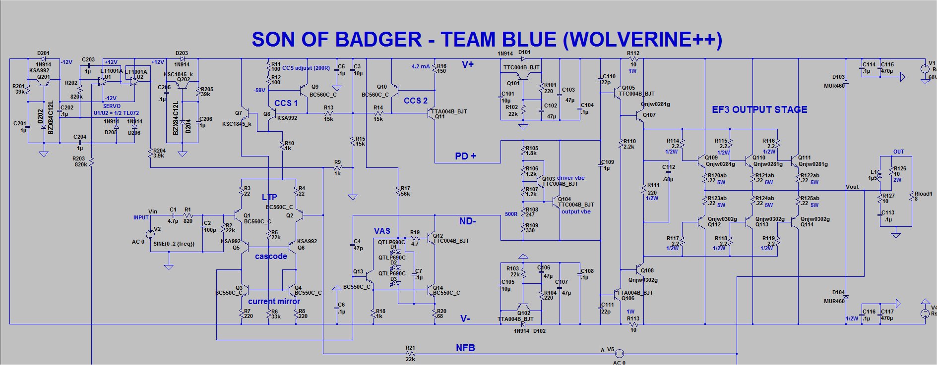
The design of the new Wolverine (Son of badger is complete)
Just waiting for OS'S final review.
Many improvements in this design over the HB.
DIYA store "Wolverine" (Son of Badger) .... suggestions ??
DIYA store "Wolverine" (Son of Badger) .... suggestions ??
Just waiting for OS'S final review.
Many improvements in this design over the HB.
DIYA store "Wolverine" (Son of Badger) .... suggestions ??
DIYA store "Wolverine" (Son of Badger) .... suggestions ??

i have always liked pnp input stages and npn VAS.....
if i were to redesign the old honeybadger that is how i will do it, again Ostripper hit it good...
if i were to redesign the old honeybadger that is how i will do it, again Ostripper hit it good...
That schematic is completely out of date.i have always liked pnp input stages and npn VAS.....
if i were to redesign the old honeybadger that is how i will do it, again Ostripper hit it good...
- Home
- Amplifiers
- Solid State
- diyAB Amp The "Honey Badger" build thread