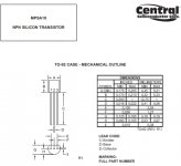
Thanks guys. This data sheet confused me. Looked as if it was showing rounded side facing out.
It is the flat side you see in that datasheet 🙂
It is the flat side you see in that datasheet 🙂
Thanks, I see it now... I thought the alternate view was the "top view". I see now that it's the bottom view.
The good news is that I've solved my LTP dilemma , and can order some parts to proceed. It's been too long, and needs to get finished! LOL.
Look at the front view carefully and you will see double lines on the sides.Thanks guys. This data sheet confused me. Looked as if it was showing rounded side facing out.
If the round face was facing you they would only be single lines.
P.S. I have nearly 1000 of these in stock if anyone is having trouble getting them.
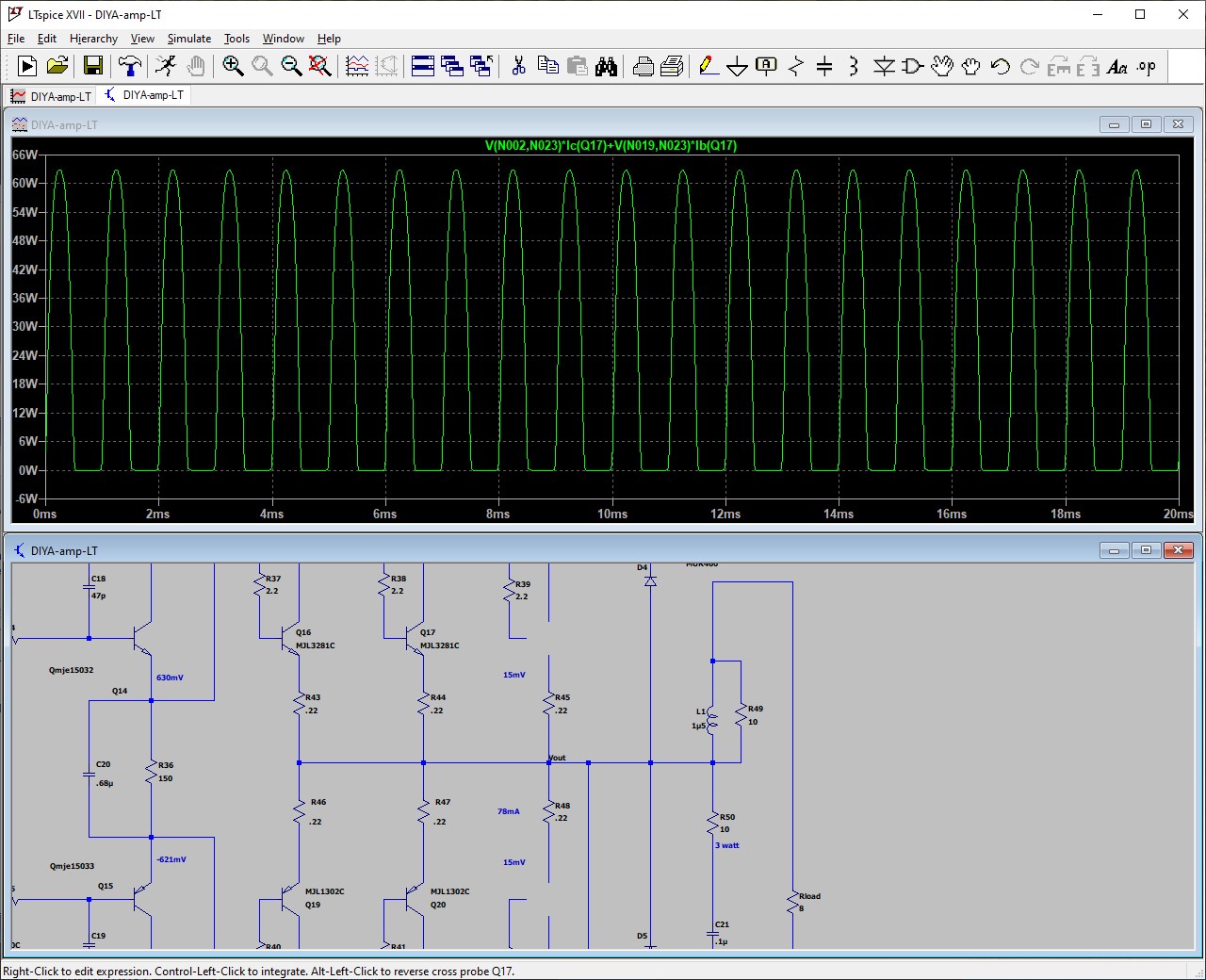
How to make it run with only two pair of transistor? I only need 100W. Power supply is 65 VDC (from 47 VAC).
I play around LTSpice for hours but it keeps pushing the remaining two pair to handle the load of last missing pair (from the usual 40W ish each transistor to 60W ish each)
Any suggestion is appreciated
I play around LTSpice for hours but it keeps pushing the remaining two pair to handle the load of last missing pair (from the usual 40W ish each transistor to 60W ish each)
Any suggestion is appreciated
You should understand how the power is generated and dissipated on output transistors.
If you just reduce the number of transistor pairs the current will normally be handled by remained transistors.
If you wanna less power on the same speaker impedance just lower the rails voltage. +/-45V should be enough for 100W/8R Badger, in my rough judgment.
And possibly some resistances should be lowered also.
Hi all, i'm looking at building the honey badger to run my new speakers. They're 8R speakers with dips down to 2.5R. They have a max power handling of 350w.
I've been reading through this thread to get an idea of what driver and output transistors and transformer voltage to use for this.
But one problem I've had is a lot of the transistors mentioned are now discontinued. But I have come across MJL21193/21194 in one of the posts for driving difficult loads. And I currently have MJE15032 / MJE15033 as the driver. Will this be okay? Only downside is they're out of stock on mouser till December, so if anyone has any other ideas I'm all ears... or eyes.
Also i have an 800VA 2x45v transformer sitting at home already, Will this be fine when driving these speakers? Or should i invest in a 2x35v or 2x40v transformer?
Thanks
Ben
Take aook at the MJL4281A and MJL4302AHi all, i'm looking at building the honey badger to run my new speakers. They're 8R speakers with dips down to 2.5R. They have a max power handling of 350w.
I've been reading through this thread to get an idea of what driver and output transistors and transformer voltage to use for this.
But one problem I've had is a lot of the transistors mentioned are now discontinued. But I have come across MJL21193/21194 in one of the posts for driving difficult loads. And I currently have MJE15032 / MJE15033 as the driver. Will this be okay? Only downside is they're out of stock on mouser till December, so if anyone has any other ideas I'm all ears... or eyes.
Also i have an 800VA 2x45v transformer sitting at home already, Will this be fine when driving these speakers? Or should i invest in a 2x35v or 2x40v transformer?
Thanks
Ben
Thanks Stuartmp. I found some of them on rsonline. They have a higher power handling too. So if I order a few other things to get free shipping they could be the ones
Last edited:
I used them with great resultsThanks Stuartmp. I found some of them on rsonline. They have a higher power handling too. So if I order a few other things to get free shipping they could be the ones
Well, back to the drawing board. Afters of years of on again, off again I finally powered up the first channel of my Badger. At first all seemed to go great. 62.78 volts from the power supply. 10 Ohm, 1 Watt resistors in place of fuses Sixty watt bulb in the dim bulb tester. I adjusted dc offset to ~0. Voltage across TP1 and TP 2 adjusted to about 18mv and was stable.
I removed the resistors and installed the fuses, and (bad idea?) took the light bulb out of the transformer primary. Powered up and all was well. Removed power. Hooked up speaker and inputs. Powered up again and all seemed well until voltage at the test points started soaring - no sound. Powered down and reset r 30. Powered up again and again no sound again voltage at bias test points started up - this time taking Q16
Any thoughts as to the problem are appreciated.
Also, it seems that NJW 0281 is not available and I have no spares - is there any safe substitute - even if I replace it later when the 0281 is available?
Again thanks for any help,
Ralph
An externally hosted image should be here but it was not working when we last tested it.
diyAB Amp The "Honey Badger" build thread
Cannot set you bias with current limiting fuses or DBT installed, but both at same time caused a bigger issue.
Go from both, check it’s working, then use only the DBT, check it’s working and set bias low, 10mV or less.
Then after an hour of working properly even with low volume music.
Only then take out the DBT and set your final bias and again watch carefully for heat on heatsinks for an hour.
Only then would I feel safe connecting any real speakers.
This is my process, I’m sure others will give additional suggestions
Check the build guide, lots of options for output transistors.

Bullit is correct, what you have is a severe over bias condition. You keep cranking and it keeps limiting, then you take out the limit and poof.
when using the series dim bulb testers, i install the fuses on the boards and proceed to power up, now if the dim bulb tester glows full bright and or stays full bright and not dim after a few secs, this means that you have faults that needed to correct...
otherwise, if the build dims after, then you can proceed to dc output offset adjustments, closest to 0vdc is ideal, but +-100 mV is acceptable..
if the dco test is good, then proceed to the idle bias adjustments...this is best done when the heatsinks have become warm...retesting over and over again as the idle current goes up as the heatsinks warm up...you may have to back down....
the idle current adjustment is done to remove vestiges of crossover distortions at the 1 watt 8 ohm levels, being class AB, you really do not need more idle bias unless your heatsink is up to the job...i will not even mention the idle currents, only that cross over distortions are eliminated by idle output current adjustments...
if you do not have a scope, listening at lowest levels with no audible distortions is good enough too...
you can at this point remove the dim bulb tester...and start enjoying the music..
the correct output stage idle current is the current when the heatsinks have reach their maximum temperatures....so initially this current will be low and then becomes higher with temperature...
too much emphasis has been given to ppm distortions but not enough practical info as to building,
bear in mind too that this amp has no SOA limiter circuit built in so that shorting the speaker cables will surely lead massive smoke coming out...you do not want to try this at home..
knowing this you will come to respect the amp better...
With an amp with NFB crossover distortion is corrected by the input stage if bias setting is too low. While it will show to be gone on a scope it's not even close to ideal setting. At the bias setting suggested by Ostripper on proper heat sinks bias adjustment can't be made with a bulb limiter installed. That's just begging for trouble.
yes, trying to adjust the output stage idle bias with the dim bulb tester in circuit, you will notice that it glows brighter as bias is increased....it can be done though, i have done it myself...better safe than sorry....
you can remove the bulb tethers once confident about the viability of your build...
you can remove the bulb tethers once confident about the viability of your build...
Thanks for the help - any thoughts on a substitute for the njw0281 that can be used with the 0302 - or must I change all 6 outputs?
- Home
- Amplifiers
- Solid State
- diyAB Amp The "Honey Badger" build thread