i do not see this as untrue...class A amps as in Nelson Pass amps used this arrangement, for class AB i see no point...
for class AB, the idle current can be a few mA to several amperes of current that flows thru those resistors so there will be a hit somehow...
I'm in agreement, CRC for Class A/B is not recommended or should be used.
Okay, so which is it? I think this merits more discussion.
i am amazed at how quick people are to adopt design practices that was originally meant for one amplifier class as if one size fits all....
for class AB, i would think a voltage regulator would have been better, i have seen it done on some other commercial amps in the past even and it will make better sense...
I'm in agreement, CRC for Class A/B is not recommended or should be used.
good man yourself.......😉
Jason, we really need to put the like button here so i have not to type this paragraph....😀

Okay, so which is it? I think this merits more discussion.
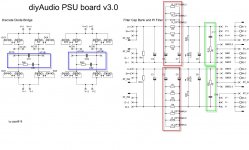
Hi Guys, Lets be sure that we are talking about the same thing.
See attached image.
Looking at the schematic, The components inside the red rectangles form a Pi filter. The create a low-pass filter and depending on the component values may attenuate the output in the order of 3 dB at 72 Hz and down 9 dB at the 120 Hz ripple frequency (with respect to the ripple voltage at the first reservoir capacitor). Attenuation is much greater at the higher rectification harmonics.
The total amount of reservoir capacitance is uncritical, but more is usually better. Those networks are there to reduce noise and 60hz Hum. So removing them will increase overall THD and THD+N
For more information on this see.
Power supply filtering confusion
or
PI-filter (or CLC vs CRC vs C)
The components inside the blue rectangles form the input snubbed network to stop the power supply from ringing as the rectifier diodes switch off halting the current flowing in the secondary windings.
For more information on this see.
Simple, no-math transformer snubber using Quasimodo test-jig
The components inside the green rectangles form the output snubbed network. They are there to damping the output from ringing.
They are probably not necessary but were included on the PSU to make it truly universal.
Last edited:
stuartmp,
no one is preventing you from doing those in "your" amp, perfectly fine if you want it....
but please allow us to do things with our amps also...
no one is preventing you from doing those in "your" amp, perfectly fine if you want it....
but please allow us to do things with our amps also...
Of course one can do whatever one wants. Simple C PS filtering will work fine but it can be improved. See discussion in this thread:
CRC power amp supply
OS explains why such PS solution he chose for GLA and Honey Badger amps and also see differences in PSRR.
cheers,
CRC power amp supply
OS explains why such PS solution he chose for GLA and Honey Badger amps and also see differences in PSRR.
cheers,
I guess it all comes down to what we all like and want.
I'm actually thinking about buying a pair of SMPS unit's my self from
SMPS500QRv3 | Connex Electronic
I like the fact that they are small & "should" work. I know about 15 years ago we all hated SMPS, but as time went by, the technology and effort put into better designs really helped.
It's 2021 so I think I shall try it.
SMPS have gone down in prices and improved reliability, i am incline to use them a lot going forward, the thing with these bricks is derate them and never used them at maximum specs...
Hi guys, can one help with a small info, I am building the badger and unfortunately the output transistors NJW0281 / NJW0302 (TO-3P) in the build guide were not available...
Are the NJW0281G/NJW0302G direct replacements (new version?) for the NJW0281/NJW0302?
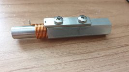
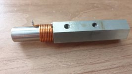
Those of you winding your inductors... I read through many threads and watched many videos. If you have a scope and a signal generator, I found this one to be the easiest, for me, to do: How To Measure Inductance - Daycounter
Has the math and a calc if you wish to forgo the algebra. Mine are both at 1.53uH. That was about 15 turns around a 12.4mm core.
Has the math and a calc if you wish to forgo the algebra. Mine are both at 1.53uH. That was about 15 turns around a 12.4mm core.
Nice... Do you have any photo that you can share.Those of you winding your inductors... I read through many threads and watched many videos. If you have a scope and a signal generator, I found this one to be the easiest, for me, to do: How To Measure Inductance - Daycounter
Has the math and a calc if you wish to forgo the algebra. Mine are both at 1.53uH. That was about 15 turns around a 12.4mm core.
Last edited:
Quote: Are the NJW0281G/NJW0302G direct replacements (new version?) for the NJW0281/NJW0302?
The parts are identical - the "G" means lead free I think, which has no bearing on the electrical spec.
The parts are identical - the "G" means lead free I think, which has no bearing on the electrical spec.
Quote: Are the NJW0281G/NJW0302G direct replacements (new version?) for the NJW0281/NJW0302?
The parts are identical - the "G" means lead free I think, which has no bearing on the electrical spec.
Yes, they are same.
Sajti
Nice... Do you have any photo that you can share.
What do you want to see?
Last edited:
I was interested in what the final inductor looked like.What do you want to see?
Sure, I used a cordless drill and a center punch because of the knurling (grips the wire) I chucked the wire and the punch in the drill then ran it for a few turns to get a good grip, then just held the wire spool in my hand and pulled down and back toward the check and spooled it slow. Worked pretty good I think.
- Home
- Amplifiers
- Solid State
- diyAB Amp The "Honey Badger" build thread


![20210110_153506[1].jpg](/community/data/attachments/822/822074-ace0ac16e70218e5c45af00480d68718.jpg?hash=rOCsFucCGO)
![20210110_153513[1].jpg](/community/data/attachments/822/822089-8155f3b5b5ba165a5ab8e38622e25e73.jpg?hash=gVXztbW6Fl)
![20210110_153522[1].jpg](/community/data/attachments/822/822114-8c8c05fb30cce170927bc5a0fa7b0468.jpg?hash=jIwF-zDM4X)