1. The 47pf Silver Mica caps next to power resistors, how did you guys soldered these because these are quite big and do touch the resistors that might get quite hot during use and I don't really want that, I want to solder these flat to the PCB but that will make the legs a big longer, does it matter if the leads a longer and by that I mean like 3-5 mm long.
Here's how I did it.
2. The input pairs of transistors how recomended is to match gaine these? i don't really own a measuring instrument to do that at the moment, I am aware that it might cause some bigger offset if these are not well matched, but is that a big concern?
The parts were bought from RS Components in a larger "" lot"" (200 pieces) so I think might be from the same batch.
I haven't matched mine.
Is there anyone who have a pair of these PCB's too much ?
They should be back in the diyAudio store soon.
They should be back in the diyAudio store soon.
Okay - that sounds good 🙂
I have asked DIYaudio store month ago and by that time they didn't know when the PCB' would be back....
When I get lucky one day and get a pair of these pcb's, then I will create 2 monoblocks and build aluminium walls in each cabinet between the transformer and everything else in the complete power amplifier.
The transformer radiate some magnetic field that can turn into hum.
Aluminium is paramagnetic and won't shield efficiently from magnetic stray. You'd better use ferromagentic shielding, such as steel.
Best regards!
Hi, one question I have regarding the C20 from the HB, the BOM says that we can use from 0.68uF to 2.2uF, the one that is specified exactly is 1uF, is there any specific reason that who made the BOm chose this value ? I am asking because I have in my stock 1.5uF at 100V from Kemet and if some have noticed any difference in sound if we use a lower or a higher value what would be the best choice?
Thanks in advance.
Thanks in advance.
C20 helps suck out some charge from the bases of the output devices when fast signals pass through.
Too small a value may allow cross conduction in the outputs.
I don't know what happens if C20 is too big. Maybe too big can never happen?
At least one other designer added a damping resistor in series with this capacitor and it was fine tuned to <1r0, so it seems he found some effect that needed to be optimised.
I don't know what symptoms to look for if the wrong damping value were chosen.
Thanks Andrew, so 1.5uF should be fine to use, and thanks for the transistors, I received the anvelope, allready soldered the BF244A and two k170A, now it only remains to get the BL ones.
Regards, Florin
Regards, Florin
Last edited:
Heatsink for the Honey Badger 🙂
2 years ago I found this heatsink on a ham radio market and was used in some solar inverter equipment.
The weight was around 20 Kg.
So I got it cut in 4 pieces og 5 Kg each 🙂
I think there is no need for cooling fans here! Haha!
Now each part is 300mm long, 150mm high and 80mm deep. They can handle around 1,3 Kw heat each.
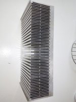
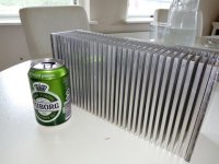
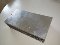
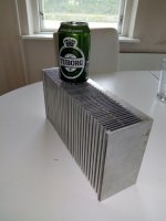
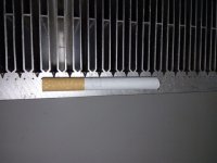


The gaps between the fins make it look like this heatsink was designed to be fan cooled.
If passive I cannot see how it can possibly achieve 1300W dissipation with a delta T at any useful value.
If passive I cannot see how it can possibly achieve 1300W dissipation with a delta T at any useful value.
Well I was told, that the could handle 1300 Watt. 🙂
He did not mention anything about fan cooling, but anyway - I think they will be good enough in passive for the Honey Badger 🙂
He did not mention anything about fan cooling, but anyway - I think they will be good enough in passive for the Honey Badger 🙂
When I see what other heatsink there are been used for the HB, then I think there is nothing to be afraid of 🙂
It's also material with weight of 5 kg for one HB pcb.
If you look at the picture with the cigaret, you see the top of the surface mount which are 20 mm thick.
If you look at the picture with the cigaret, you see the top of the surface mount which are 20 mm thick.
Modushop 300x40x210 0.2C/W, 1.05kg
Modushop 300x40x120 0.4C/W, 0.64kg
Fisher SK56/200 300x40x 200 0.3C/W 3.52 kg
Haven't found new books on thermal design to support modushops data must be a new cooling design and it is cheap.
Andrew care to explain?
Lähetetty minun ONEPLUS A3003 laitteesta Tapatalkilla
Modushop 300x40x120 0.4C/W, 0.64kg
Fisher SK56/200 300x40x 200 0.3C/W 3.52 kg
Haven't found new books on thermal design to support modushops data must be a new cooling design and it is cheap.
Andrew care to explain?
Lähetetty minun ONEPLUS A3003 laitteesta Tapatalkilla
tonza. I don't know where you get your information, but it's not correct.
Modushop 300x40x210 is 2.6kg.
Modushop 300x40x120 is 1.5kg.
Fisher SK56/200 is 2.9kg.
Modushop 300x40x210 is 2.6kg.
Modushop 300x40x120 is 1.5kg.
Fisher SK56/200 is 2.9kg.
Modushop.pl Take a look
Tme.eu "gross weight" ok.
Thanks for you correction audiosan with respect.
Lähetetty minun ONEPLUS A3003 laitteesta Tapatalkilla
Tme.eu "gross weight" ok.
Thanks for you correction audiosan with respect.
Lähetetty minun ONEPLUS A3003 laitteesta Tapatalkilla
Inrush current limiter
I am referring to an older post #2410. I used the schematic for my inrush current limiter board as shown below (supports also other functions).
The schematic originally shown in #2406 didn't work for me. I had issues with not reaching the initiating current of the thyristor and also the problem that the relay is often not "thrown" into the other state to engage lock. A snubber could solve the first but not the lock problem.
The schematic proposed on 2410 had no initiating current problem but still the lock issue.
By adding the additional capacitor which is charged by 180k to not cause the relay to switch and is discharged via the diode and the conducting thyristor applies the holding current over some 50Hz periods.
Now its working fine!


Circuit in post 2406 is a clever circuit ..but can get better with this modification .. this way ... even after a quick power failure the timer is reset ..
I am referring to an older post #2410. I used the schematic for my inrush current limiter board as shown below (supports also other functions).
The schematic originally shown in #2406 didn't work for me. I had issues with not reaching the initiating current of the thyristor and also the problem that the relay is often not "thrown" into the other state to engage lock. A snubber could solve the first but not the lock problem.
The schematic proposed on 2410 had no initiating current problem but still the lock issue.
By adding the additional capacitor which is charged by 180k to not cause the relay to switch and is discharged via the diode and the conducting thyristor applies the holding current over some 50Hz periods.
Now its working fine!


Hi to all, help me with an advice, I have just received my Toroidal transformer for my Honebadger , it is a 35 volt dual secondaries , I did not buy the 800VA version because of the price unfortunately so the one I have is rated for 600VA, my issue if we can call it like that is that it has thermal fuses in the secondaries rated at 10A and each 35V side can deliver 8.5A, now with the power supply board fully equiped with 4 X 12000uF/80V caps is there any danger in triping these thermal fuses? I was expecting one that has the thermal fuse in the primary.
I do have the soft start board working and ready to use but now I am worried because the caps will take quite some current to charge initially.
The transformer part number is : TTS600/D230/35-35V
Thanks,
Florin
I do have the soft start board working and ready to use but now I am worried because the caps will take quite some current to charge initially.
The transformer part number is : TTS600/D230/35-35V
Thanks,
Florin
- Home
- Amplifiers
- Solid State
- diyAB Amp The "Honey Badger" build thread