No. it's about current capability.That is linearity, except for a higher word-count.
Also, linearity sounds fantastic.
This is an aspect of amplifier building that most Members here are completely oblivious to.
If current capability is inadequate, the maximum output voltage drops excessively when current demand increases.
It is not about linearity, as in low levels of distortion at low signal currents.
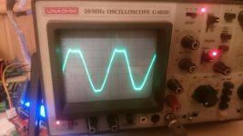
Did some testing on my Badger today. Got around 100v p2p into a 8r load before clipping.
I noticed that it has a strange behavior when it starts clipping. What can cause this?
Just before it enters clipping it seems to oscillate a bit on the positive pulse.
When testing in 4r I blew up my test resistor. 😛
I noticed that it has a strange behavior when it starts clipping. What can cause this?
Just before it enters clipping it seems to oscillate a bit on the positive pulse.
When testing in 4r I blew up my test resistor. 😛
Attachments
Would we call it "current headroom"?No. it's about current capability.
This is an aspect of amplifier building that most Members here are completely oblivious to.
If current capability is inadequate, the maximum output voltage drops excessively when current demand increases.
I'm fairly sure that it has something to do with the transformer amperage capacity as well as the output device's current vs hfe graph (a linearity behavior). But, what other parts/locales need checked?
Perhaps a checklist would help explain it?
Did some testing on my Badger today. Got around 100v p2p into a 8r load before clipping.
I noticed that it has a strange behavior when it starts clipping. What can cause this?
Just before it enters clipping it seems to oscillate a bit on the positive pulse.
When testing in 4r I blew up my test resistor. 😛
way back in post #570 I had the same issue. That is when OS came up with the diode clamp. I never did install it on my Badger. I doubt it will ever be an issue since this thing is so loud I will likely never clip it in the real world. If you have the newest boards I think the clamp option should be there.
no. It's not about spare current capacity.Would we call it "current headroom"?
I'm fairly sure that it has something to do with the transformer amperage capacity as well as the output device's current vs hfe graph (a linearity behavior). But, what other parts/locales need checked?
Perhaps a checklist would help explain it?
It's about the current actually being delivered. That is not headroom.
That's a horrible overload/clipping profile. 100Vpp is equivalent to 156W into 8r0. What were your supply rails while doing this?Did some testing on my Badger today. Got around 100v p2p into a 8r load before clipping.
I noticed that it has a strange behavior when it starts clipping. What can cause this?
Just before it enters clipping it seems to oscillate a bit on the positive pulse.
When testing in 4r I blew up my test resistor. 😛
The ripple/oscillation is indicative of a lack of stability margin somewhere in the system. If that were continued, it could cause severe overheating and eventually a blow up. This is the area where I am particularly weak. I cannot identify the part that needs compensation and cannot select suitable compensation component values, because I don't understand enough of the AC operation.
The supply rails are 62-63V on idle. l didn't measure them while clipping, the transformer is 800VA and capacitance 40kuF so it should be able to keep up.
I did blow a horn tweeter with it earlier, now I use the slew with 80v rails for those speakers. Unfortunatly I can't do any more testing at clipping to find out more since I blew up one of my test resistors when testing in 4r. I got 267W at clipping into 4r.
It's not a biggie since I now use the amp in a different setup where I pobably won't clip it again but I would like to do something about the clipping behavior to get peace of mind.
measure the drooped supply rails before clipping.
I would not leave a clipping amplifier driving any load. Overheating could be very rapid.
Music clipping is usually only on very fast short period transients. The clip happens and returns to non clipped in a few micro-seconds, or less. It's the tolerance of semiconductors to micro-second transients that stops our creations blowing up.
Compare the DC or 1 second SOA to a 1ms and to a 1µs SOA.
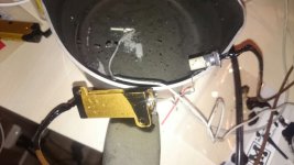
I posted a pic of a cheap 4r0 225W dummy load resistor.
I have 4 of them to allow lots of combinations for different tests.
I also have lot's of 10r, 20r & 50r in 5W packages for special loads.
I have 4 of them to allow lots of combinations for different tests.
I also have lot's of 10r, 20r & 50r in 5W packages for special loads.
where are the pictures andrewt? i am eager to see.....
I posted a pic of a cheap 4r0 225W dummy load resistor.
I have 4 of them to allow lots of combinations for different tests.
I also have lot's of 10r, 20r & 50r in 5W packages for special loads.
50Vpk from a quiescent rail of 62 to 63Vdc is reasonable.The supply rails are 62-63V on idle. l didn't measure them while clipping, the transformer is 800VA and capacitance 40kuF so it should be able to keep up.
I did blow a horn tweeter with it earlier, now I use the slew with 80v rails for those speakers. Unfortunatly I can't do any more testing at clipping to find out more since I blew up one of my test resistors when testing in 4r. I got 267W at clipping into 4r.
It's not a biggie since I now use the amp in a different setup where I pobably won't clip it again but I would like to do something about the clipping behavior to get peace of mind.
I typically get 52Vpk from a 59Vdc supply rail, or 41Vpk from a 50Vdc supply rail. Droop plus amp loss of 7V to 10V
Some Builders are happy with a droop plus amplifier loss of >20V. That is a disaster.
I tested that Sugden into 4r0 and it falls into disaster category for a 4r0 loading.
Better into 8r0 and better still after I modified it to make it current capable.
Last edited:
The supply rails are 62-63V on idle. l didn't measure them while clipping, the transformer is 800VA and capacitance 40kuF so it should be able to keep up.
I did blow a horn tweeter with it earlier, now I use the slew with 80v rails for those speakers. Unfortunatly I can't do any more testing at clipping to find out more since I blew up one of my test resistors when testing in 4r. I got 267W at clipping into 4r.
It's not a biggie since I now use the amp in a different setup where I pobably won't clip it again but I would like to do something about the clipping behavior to get peace of mind.
Did you follow the link I gave above to post 570? OS gave a fix for the latching.
i building the amplifier howto get dc 0mv at loadspeaker output
All components from bought from mouser for soft start to universal dc supply v3 building two honey badgers with dc 63.1v 0 -63.1 last 3 months stayed to the point when adjusting bias with mje15032 and mje15033 installed two 68 ohm from the emitters two the output settled at 0.55 and tp1 tp2 1.1v .q1q2 SS9014DBU re hfe 560 on dmm about the same with transistor tester dbu re15re16 121 handpicked from 1% q3,4 KSC1845FTA r2021 handpicked 220.1 ohm KSA1015GRTA hfe 394 q7,8 KSC1845FTA q9-KSA992FBU hfe 480 q10-KSA1381ESTU hfe 147 q11,q12,13 KSC3503DSTU picked same hfe 103 dmm only and diode tester . solder q17,18 q20,21 mg6331-r mg9411-r ihave 10 of each from rsonline .mica washer to heatsink . DC out 5v cannot adjust stays 5v i can increase bias but with max 504ohm r46r47 measure mv 22.5 mv r43 22.6mv r44 36.5 mv . looked if pressure on q17 was not good remounted all about the same . i chose only 2 pairs witch were closest dmm diode meter and on transistor tester. one evening i was a little druck and irrateded no bulb, boom resistor and 4a fuse . my second badger built the same components but it,s completly different dc out over 20v only drivers so i stopped there 40w bulb and 10ohm resistors after fuse, can you help me howto get dc about 0v so i can adjust r14 but not r17 dc . . help needed & apprecieted.
All components from bought from mouser for soft start to universal dc supply v3 building two honey badgers with dc 63.1v 0 -63.1 last 3 months stayed to the point when adjusting bias with mje15032 and mje15033 installed two 68 ohm from the emitters two the output settled at 0.55 and tp1 tp2 1.1v .q1q2 SS9014DBU re hfe 560 on dmm about the same with transistor tester dbu re15re16 121 handpicked from 1% q3,4 KSC1845FTA r2021 handpicked 220.1 ohm KSA1015GRTA hfe 394 q7,8 KSC1845FTA q9-KSA992FBU hfe 480 q10-KSA1381ESTU hfe 147 q11,q12,13 KSC3503DSTU picked same hfe 103 dmm only and diode tester . solder q17,18 q20,21 mg6331-r mg9411-r ihave 10 of each from rsonline .mica washer to heatsink . DC out 5v cannot adjust stays 5v i can increase bias but with max 504ohm r46r47 measure mv 22.5 mv r43 22.6mv r44 36.5 mv . looked if pressure on q17 was not good remounted all about the same . i chose only 2 pairs witch were closest dmm diode meter and on transistor tester. one evening i was a little druck and irrateded no bulb, boom resistor and 4a fuse . my second badger built the same components but it,s completly different dc out over 20v only drivers so i stopped there 40w bulb and 10ohm resistors after fuse, can you help me howto get dc about 0v so i can adjust r14 but not r17 dc . . help needed & apprecieted.
Check all of your transistors to make sure you have PNP where PNP goes and NPN where NPN goes and insure they are all facing correctly. Double check that all diodes are facing the correct way. Reflow all of your solder joints to insure no cold joints. Check for solder bridges. If you know how, do a diode test on all transistors. This may reveal a bad device. Once you have confirmed all of that, if you still have DC offset you may need to mark up a schematic with voltages.
ok
diodes are facing right way i will do the transistor diode test , i made a degree in electronics,computer mechanic 22 years ago. Thanks still4given , allways enjoying your posts. i post later the results.
diodes are facing right way i will do the transistor diode test , i made a degree in electronics,computer mechanic 22 years ago. Thanks still4given , allways enjoying your posts. i post later the results.
one evening i was a little druck and irrateded no bulb, boom resistor and 4a fuse .
I assume you meant to write "drunk". Very bad thing to do when building amplifiers and working with electricity.
 . Also bulb tester is invaluable, even when a small change like wiring is done, I use bulb tester. Saved me a couple of amps atleast!
yeah no to alcohol. Took some on my 40 birthday , normally i don't use.
I had the bulb in series today as always but once.
the board bends a little while measureing red light come on. Find out q14 was short cutted. soldered it away from board ,now its okay with dmm and transistor tester . I will post later on project (wife comes home, so kitchen needs little cleaning)
I had the bulb in series today as always but once.
the board bends a little while measureing red light come on. Find out q14 was short cutted. soldered it away from board ,now its okay with dmm and transistor tester . I will post later on project (wife comes home, so kitchen needs little cleaning)
Would adding a small cap (10-20pF) across R24 (820 ohm) in TMC would reduce chances for oscillation?
In two pole compensation it helps but I don't know if it would work in TMC.
cheers,
.
In two pole compensation it helps but I don't know if it would work in TMC.
cheers,
.
I'm building a new Honey Badger, and I'm thinking about using these, fulfilling ostripper's wish from post 1167:
http://www.farnell.com/datasheets/866313.pdf
What variations from the specs in the BOM (if any) would I need to make to tweak the amp for these?
http://www.farnell.com/datasheets/866313.pdf
What variations from the specs in the BOM (if any) would I need to make to tweak the amp for these?
ongoing second badger
1 badger is good. I do not own a oscilloscope so no input output waves comparsion , onto my second i can adjust output emitter voltage q14,q15 but output is rising. Changed q1,q2 to ss9014cbu and q5,q6 ksa1015y both matched because the old q2 was faulty 9.1v bc be now be 0.66V .
I,m doing this slow put the voltages on spreadsheet and component values.And post them here when finished. For presision resistors r15,r16 ,r20,21 from 10 pcs 0.1% handpicked. Put some euroblocks for q13,q14,q15 and a pair of old pentium prosessor coolers drilled and tapped for faster mount. 1 would do but 2 for looking at option for q14,q15 i have a many 2sc5171,2sc1930 and a few 2sa1837, 2sc4730 toshibas.
Read cornell and bobs books in designing amplifiers a few times. But my memory can't cope with all , the referecenes are there!. Not tested in real world while reading.Maybe to much reading Nietzsche 20 years ago
f***** my brain!
The chassis is almost done diy with 4 heatsinks V 6506K Profile heat sink, 100x160x40mm, 0.7K/W 2 per side cheap under 50 euros .Bought transistors in 100 insted of few or 10 from mouser for the future projects and badger. i will need the 21 century protection board for my mind and loved loudspeakers. I like the sanken 2 mount hole caseing over mg6331s ,1 will do but 2 ..
I'm slowing down but getting to my golds the further they seem, i admit i'm addicted .now back to work.
Not yet the mg 6333 is not available in europe from rsonline or farnell until 14.3.2016 but the 9413 are. Now back to work
- Home
- Amplifiers
- Solid State
- diyAB Amp The "Honey Badger" build thread