Any 200v+ PRV (peak reverse voltage) , low reverse leakage in the uA range.
There are a lot of choices.
OS
There are a lot of choices.
OS
Sorry, I don't know how to look for that. Could you please give me an example? Preferably a Mouser or Digikey part. Would a 1N4007 work?
Thanks, Terry
Thanks, Terry
Last edited:
Actually ... I was wrong 😱 , look for nA leakage.
I had to bring my files on this back out.
PS - all the 1Nxxxx's suck ! (for this app.)
OS
I had to bring my files on this back out.
PS - all the 1Nxxxx's suck ! (for this app.)
OS
Bav21 is 250V
That's the one... BAV21 ... I even have the model for it.
Picture is below. Arrows point to anode (collector of Q10) and
cathode (Base of Q9).
Be sure to shrink wrap the leads of the diode so as not to
touch any other trace.
OS
Attachments
If the two leads are left long, you can add the diode on the back of the PCB and crop the remaining lead after soldering the diode.
Born New Year's Eve
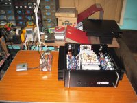
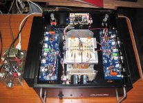
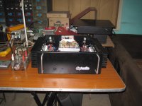
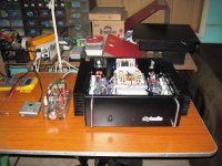
this is my Badger, CCS set to recommended setting, bias pot to 500ohms,
output offset was very low and close to zero mV....
Sound reminds me of my Leach amp, no desire to increase bias,
heatsinks are colder than expected.....congrats to Ostripper for a very nice design....
source is a MD player, since output is low, i used my tube preamp designed for these type amps....
these amp is very quiet, no part of the psu is connected to chassis....
i might connect a 10 ohm to chassis later on...
Attachments
Very nice build , AJ .
Put some boosted supplies on that badger (below 1) ....
Even as this is my "old amp" , the "blameless"
is one hell of a performer.
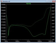
It actually can be improved ... I simulated a badger/triple ... OMG ! (below 2)
The DIYA blameless does a sweet 10ppm/8R. Without boosted supplies, the
badger still does 115db PSRR. At these levels , one most likely would not
notice.
Mr. Self should buy himself a couple Badgers ..... 😀
OS
Put some boosted supplies on that badger (below 1) ....
Even as this is my "old amp" , the "blameless"
is one hell of a performer.
It actually can be improved ... I simulated a badger/triple ... OMG ! (below 2)
The DIYA blameless does a sweet 10ppm/8R. Without boosted supplies, the
badger still does 115db PSRR. At these levels , one most likely would not
notice.
Mr. Self should buy himself a couple Badgers ..... 😀
OS
Attachments

Very nice build , AJ .
OS
thanks OS, i am going to build another one for myself, this time with higher rails and bigger psu...
if i may, i have some suggestions based on experience building this board for future revisions,
1. the pads for jumpering C, R, or Z needs to be exposed, i had to scrape the solder mask to make connection...
2. solder pads for to-92's can be a bit smaller, and associated traces narrower since they are not carrying big currents......
about the baker clamp, suggest that you incorporate in your new board revision in future...
this board will work the first time if everything was fallowed to the letter....
again yours is a very good design indeed, i will recommend to friends at another forum to try....😀
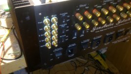
Tony, how much will you get for that in Manila ?
Did you source the case there or off the forum ?
Did you source the case there or off the forum ?
Tony, how much will you get for that in Manila ?
Did you source the case there or off the forum ?
the casing is made of 2mm aluminum cut and bent as per my design, even the heatsinks are local purchase, you can by them in foot lengths...
the stainless steel handles are from a local hardware store...
total cost for the casing is about U$100....
...
total cost for the casing is about U$100....
I think I need to move to Manila. 😉
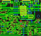
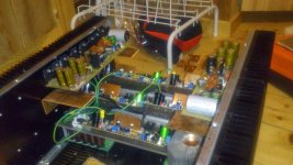
Dear AJT , all of your suggestions were added to the Badger in
V2.4 and submitted to Jason.
The pads/traces are kept "fat" , the Badger PCB can actually be
reworked several times.
v2.4 badger (w/soldermask) below.
PS - I think you are the first to mount horizontal - I designed with this "option" .. but
never have seen it in a build - looks nice(est) !!
OS
V2.4 and submitted to Jason.
The pads/traces are kept "fat" , the Badger PCB can actually be
reworked several times.
v2.4 badger (w/soldermask) below.
PS - I think you are the first to mount horizontal - I designed with this "option" .. but
never have seen it in a build - looks nice(est) !!
OS
Attachments

Last edited:
... I simulated a badger/triple ... OMG ! (below 2)
OS
Ostripper,
If you were to post such a circuit I would be sure to build a pair!
Last edited:

Hi cod3gen,
are you using 4 output pairs?😀
What resistor value did you use for R27 ie 68 or 100R?
Regards
are you using 4 output pairs?😀
What resistor value did you use for R27 ie 68 or 100R?
Regards
Dear AJT , all of your suggestions were added to the Badger in
V2.4 and submitted to Jason.
The pads/traces are kept "fat" , the Badger PCB can actually be
reworked several times.
v2.4 badger (w/soldermask) below.
PS - I think you are the first to mount horizontal - I designed with this "option" .. but
never have seen it in a build - looks nice(est) !!
OS
thanks OS.....

- Home
- Amplifiers
- Solid State
- diyAB Amp The "Honey Badger" build thread