Is this next 'project' one to retro-fit the local town movie theater with a new sound system? 😀 Not sure what version PCB's I got, but it will be awhile before I can start construction on it due to a family move and they're packed away. The components arrived last week from Mouser. Now I see ostripper is making mods already! How can I keep up?! 😱 Looking forward to the build though.I'm thinking my next project will be a liquid-cooled home theater amp with 5 Honey Badger boards...
Rick
Now I see ostripper is making mods already!
Absolutely NOT ! "If it works - don't fix it"
These are just "ease of construction" and physical layout tweaks ...
The "mods" are pre-built in to the PCB's .
"DIYA-AMP -construction-advanced-options" , which I will update (done) , explains the madness. This allows the use of a wider variety of components.
"CCS adjust" alone can allow the badger to use FET input stages or a dozen different BJT pairs.
My Bass badger will be quite different from my main stereo pair. My 4th badger will be the first FET badger. If this is acceptable or superior it will be ported to my main stereo pair. All on the same boards ! 😎
OS
Attachments
Absolutely NOT ! "If it works - don't fix it"
These are just "ease of construction" and physical layout tweaks ...
The "mods" are pre-built in to the PCB's .
"DIYA-AMP -construction-advanced-options" , which I will update (done) , explains the madness. This allows the use of a wider variety of components.
"CCS adjust" alone can allow the badger to use FET input stages or a dozen different BJT pairs.
My Bass badger will be quite different from my main stereo pair. My 4th badger will be the first FET badger. If this is acceptable or superior it will be ported to my main stereo pair. All on the same boards ! 😎
OS
What about a version with lateral mosfets at the output?
Renesas and Exicon has these in mass production and apparently d-class has its own trully cheap 10A lateral mosfets. I do not know how good these are but Exicon is not bad and Renessas pretty acceptable although not as good as old Hitachi.
In my personal opinion laterals as output devices offer more advantages than jfets at the input but that depends what is one's hierachy of preferences.
cheers,
Janusz, Laterals have a Vgs requirement similar to the Vbe of a BJT. I'd bump the gate (was base) stoppers R27-42 up to 100-200R and you should be good to go. You'll have to make flying leads since the pin order is different.
I am doing the same with some Leach boards once the chassis gets here.
I am doing the same with some Leach boards once the chassis gets here.
Last edited:
By janusz - What about a version with lateral mosfets at the output?
I'd love to ... but drain and source are reversed from where it would have to be on this PCB.
http://products.semelab-tt.com/pdf/magnatec/ALF08N16V%20ALF08N20V.pdf
(Not a BJT drop in replacement).
With flying leads (short ones - (gate) stopper in close proximity to the gate) , the circuit would easily drive Laterals. Would not look as good.
I would ignite a "war" to say either a MOSFET or a BJT has "better" sound - won't go there 😀 ...
OS
OS, I'm less than an hour north of you in Glens Falls. Once I get my Lateral Leach together we can have a shootout. 😉
Fair enough OS. I should have put a smiley after that sentence. I really wasn't complaining! Whether it's an ease of construction, or physical layout tweaks, I consider it a change to the original version of the PCB. I'm sure I can deal with it come time for the build. But that's a couple of months off, if not longer due to my situation. I'll just have to re-read the salient posts in this thread for those comments. (good luck in finding those 🙂) I sure would hate to fry something because I forgot a jumper that wasn't marked properly, or had changed.😉😀Absolutely NOT ! "If it works - don't fix it"
These are just "ease of construction" and physical layout tweaks ...
The "mods" are pre-built in to the PCB's ....OS
OS, I'm less than an hour north of you in Glens Falls. Once I get my Lateral Leach together we can have a shootout. 😉
Cool .. I'm right at I-90/ everett rd./central (Albany). I am out now (with that bike cart) for more E-waste - About all I need is a chassis. I have 100K of capacitance , 2 toroids , 25A bridges, (the badger PCB's). So very close ...
Tomorrow, I will have that Mouser cart finished (about <$30 per Badger) !
That comes out to about $103-105 per stereo pair including shipping (US) and the DIYA store boards.
OS
I'd love to ... but drain and source are reversed from where it would have to be on this PCB.
http://products.semelab-tt.com/pdf/magnatec/ALF08N16V%20ALF08N20V.pdf
(Not a BJT drop in replacement).
With flying leads (short ones - (gate) stopper in close proximity to the gate) , the circuit would easily drive Laterals. Would not look as good.
I would ignite a "war" to say either a MOSFET or a BJT has "better" sound - won't go there 😀 ...
OS
Board modification - that's what I meant. Apart from different pinout one must protect gate from getting more than 12V or so depending on a chosen mosfet so zener plus diode have to be fitted - one for each transistor.
I like laterals mainly because of their negative temperature coefficients. Sonics are always subjective but smell of burning output transitors is not.
cheers,
PS where one can buy ALFETs? I heard that that they are a touch more reliable than Exicons but I do not know if it's true.
Not sure if this is applicable as I have a v2 board, but I ran into some more tight spots.
Holes for Q13 needed to be drilled out to 1mm
C11 and C13 could have another pad for 7.5 mm LS; holes could be larger
Holes for Q13 needed to be drilled out to 1mm
C11 and C13 could have another pad for 7.5 mm LS; holes could be larger
Board modification - that's what I meant. Apart from different pinout one must protect gate from getting more than 12V or so depending on a chosen mosfet so zener plus diode have to be fitted - one for each transistor.
Resistor + zener (protection) - I was one of the first to recommend this to the "quasi amp" thread . I could modify this board in 20 minutes to accommodate the laterals+ zener protection. I really want to stick with standard BJT's , as they can ABSOLUTELY make for a true audiophile experience. The 2SC5200 /1943 pair are just 2 US$ apiece now, njw's are just $1.60 USD - BJT's are the "economy" choice.
Believe me , NO smell of "burning amps" around here. 😀 I have to turn off the AC just to realize that there is an amp in the room (my Badger runs really cool
 )
)OS
Only problem is that the LM3886 can't handle that much voltage, so you'd either need really low-impedance on the front speakers to get the power, or run two different transformers or SMPSs to get the right voltages.That's a lot of "juice" - best left for the Canadian Hydropower.
HTPC - If I did a 4.1 or 5.1 , I'd mix 3 badgers with 2-3 lm3886 IC amps.
Example - 4.1 = 2 badger's - 2 LM3886's , separate HD "bassbadger".
Rear channels are typically closer , only L-R/R-L audio information .. A badger would be overkill.
My 2.1 setup will have a few inches of space left in the case - enough for the chips.
OS
Not sure if this is applicable as I have a v2 board, but I ran into some more tight spots.
Holes for Q13 needed to be drilled out to 1mm
C11 and C13 could have another pad for 7.5 mm LS; holes could be larger
I think they fixed that with V2.3. I have the V2.2 sprint which I have updated .. it originally had C13/17 at 1mm - 7.5 and 10mm LS. C11 /15 , 1mm hole- 5mm LS.
That is strange , the v2.3 actual boards I have ... all my caps and semi's fit with no drilling - I have no pins larger than holes and the lead spacing (semi's and caps/ resistors)- are perfect. I expect to populate these boards nearly to spec !
When I submitted my first Sprint (below-drilling text) - I did my homework (read the text-this is what sprint is set to). All drillings were .1-2mm over the largest expected component. Possibly , the outsourced PCB work was in error (there , I said it 😱) . I will update the drilling text (it actually is in spec now) for "looser" holes.
"perfection is possible"
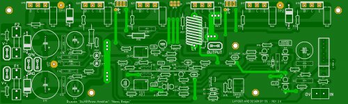
FINAL v2.4 is below. --- Zobel cap (C21) even has more room !!
OS
Attachments
Last edited:
Absolutely !! Use the little anemic 25-0-25V trafo that came with the 3886.Only problem is that the LM3886 can't handle that much voltage, so you'd either need really low-impedance on the front speakers to get the power, or run two different transformers or SMPSs to get the right voltages.
The trafo in the picture a few posts back (300VA 32-0-32VAC) , ran 5 full LM3886 channels (philips HT receiver ) . With the bassbadger , I should be able to get a full 150w to my sub (one amp -with that trafo).
OS
Last edited:
In a slightly unrelated question. . .If the separation of this amp is good now, try true dual mono power supplies!
Is it possible to increase the stereo separation of a stereo (only one transformer) arrangement by putting diodes series with R32, R33, similar to Hafler DH220's low cost virtual dual mono system?
P.S.
Of course I'd rather use real dual-mono for favorable power resources appropriate to high power amplifiers, and therefore my question above about stereo builds is actually just for fascination/curiosity.
P.P.S.
I actually haven't been soldering lately. But there has been much reinventing the wheel--Bicycle wheels, actually. They're much like power supplies in that all of the performance parameters conflict with each other, except when near a balance which is when a whole new set of parameters appears and could be optimized. Well, it is an awesome puzzle.
Last edited:
OS, Have you compared the sound of Toshiba and Fairchild versions of 2SC5200/1943? At least as Mouser the Fairchilds are slightly more inexpensive.
The curves in the datasheets seem a bit different even accounting for differing scales. The Fairchild DC current gain curves start out flat, while Toshiba's rise. Toshiba plots hfe against case temp while Fairchild plots it against junction temperature. Would that account for a difference? Doesn't seem it would.
Daniel, A closer dual mono approximation is to start at the rectifier bridges, like Pass/Thagard did for the A75. Two bridges or sets of bridges attached to the same transformer feeding their own capacitor banks.
Can someone explain the 12v - 15v option for the cascode zener diode? Not sure which value I'd want. I am using these toroids in a true dual mono.
Antek - AS-4445
Antek - AS-4445
BobEllis - OS, Have you compared the sound of Toshiba and Fairchild versions of 2SC5200/1943?
No , but I have heard the 2sc5242/a1962 (130w versions). I find a lot of these in E-waste. I think they are just in a smaller case (to-3P). The sound is the same - electrically they have higher Hfe. They bias different than the ON's or fairchilds in a badger type amp.
OS
Last edited:
Can someone explain the 12v - 15v option for the cascode zener diode? Not sure which value I'd want. I am using these toroids in a true dual mono.
Antek - AS-4445
You can use 12 , 15 or 24V as D3 - unless you have a real low Vceo LTP pair.
12 or 15 V would cover almost any BJT pair.
Nice trafo - would be a 63-65Vdc rail , perfect for some real exciting transients.
OS
- Home
- Amplifiers
- Solid State
- diyAB Amp The "Honey Badger" build thread