Oh, I thought the red markings were yours.I just copied this file from here. I don't know if the (simulated?) voltage values are correct, but I'll measure it in my build.
V across the emitter resistorWhat does "re" refer to?
If the bias voltage is set low, then the voltages in the two following stages are also low. That will reduce the bias current in both the driver stage and the output stage. You have stated that your two bias currents are low. So it follows that this is at least in part due to setting the bias voltage low.Assuming you are referring to Q13+R28+R29+R30+R31 as the "multiplier", this is exactly how the biasing of the output stage works. R30 is a trimpot (not shown correctly in the schematic), which is used to set the bias.
I doubt that. That would be twisted logic. It is either done that way because the designer thinks it improves performance, or because the designer has proved by measurement that this is the optimum for Crossover Distortion.I believe the 15 mV value is conservative for cool operation (with smallish heatsinks?). I biased mine a bit higher.
Last edited:
That allows you to calculate the base current of the +IN half of the LTP.The voltages I measured in my build are closer to -13 mV.
Use that to estimate the hFE.
Is that what you measured before you assembled?
Unfortunately with VR12 in place you cannot check the emitter currents of the LTP.
New build help
I couldn't figure out what was wrong with my first board so i built my second using identical parts as the first all measured for resistance or capacitance and simple diode test for transistors before placing.
It powered up without issue and i was able to adjust it with the safety resistors in place according to the build guide. Adjusted so across R14 reads 8.2v, Output to ground 0.000-0.001v, and TP1 to TP2 0.030v.
Let it sit for about 20 minutes, adjusting trim pots just a little every 5-10mins until it stabilized voltages. Then i powered it down and removed the safety resistors and put the fuses in place.
Powered it back up and re-adjusted to get those measurements back and let it sit, it remained stable at those readings for another half an hour.
By this time the middle VAS heatsink was very warm but not too hot to touch. All of the heatsink mounted transistors were cool/barely warm to the touch, i have a Deluxe 4U Aluminum case from DIYA and its heatsink is lightly warm.
I'm pretty new to electronics but based on the build guide and what i've read through this forum it looks like the board is good to go?
I attached a speaker i was ok with losing to the output with nothing touching input at 0v/In and i get a faint buzz or hum from the speaker. I noticed if i pass my hand a couple inches over the LTP/0v/In area that noise gets louder. It also gets slightly louder when i touch the heatsink the board and transistors are mounted to. I powered down and checked after noticing that and could not get continuity from any heatsink to any point on the card or transistors or 0v/In.
I was starting to hook an extension wire in to the 0v/In jacks on the board while it was on and i could loudly hear the wires scraping the walls going in to the 0v/In jacks amplified through the attached speaker so i stopped and removed them. I powered the amp down and attached an extension wire to 0v/In and powered it back up. The other end of the extension wire is just a cut end, sheathed still, no connector. Now the buzz is louder and the wire acts like an antenna, the buzz gets louder as i move my hand near the wire, loudest if i'm touching it. That seems way too sensitive to attempt plugging an audio source in.
I built the v2.4 boards using the BOM dated 1/16/2013.
Do my measurements look good?
Is the very high sensitivity to even the proximity of my hand normal?
How do i diagnose this buzz/hum?
Is the VAS heatsink supposed to be very warm at idle?
Lastly, if i wanted a volume knob on this amp can/how would i go about that? Something to prevent someone plugging in a device that has its volume set too loud? Or is that what a pre-amp is for?
Sorry for being noob, thanks.
There may be two different issues.
1.) the buzz+hum is likely to be a wiring fault, probably in the way the Transformer to PSU to Amplifier is constructed.
2.) the sensitivity to parasitic capacitance is possibly due to a lack of RF attenuation, or the amp is very close to oscillation.
Is the amplifier fitted to an enclosure yet? or strung out along the work bench?
Can you give measurements for H+N at the output for the different test conditions?
Have you tested output offset with the input shorted?
That all sounds reasonable. Try shorting the input (IN to 0V) and see if the hum and buzz goes away.I couldn't figure out what was wrong with my first board so i built my second using identical parts as the first all measured for resistance or capacitance and simple diode test for transistors before placing.
It powered up without issue and i was able to adjust it with the safety resistors in place according to the build guide. Adjusted so across R14 reads 8.2v, Output to ground 0.000-0.001v, and TP1 to TP2 0.030v.
Let it sit for about 20 minutes, adjusting trim pots just a little every 5-10mins until it stabilized voltages. Then i powered it down and removed the safety resistors and put the fuses in place.
Powered it back up and re-adjusted to get those measurements back and let it sit, it remained stable at those readings for another half an hour.
By this time the middle VAS heatsink was very warm but not too hot to touch. All of the heatsink mounted transistors were cool/barely warm to the touch, i have a Deluxe 4U Aluminum case from DIYA and its heatsink is lightly warm.
I'm pretty new to electronics but based on the build guide and what i've read through this forum it looks like the board is good to go?
I attached a speaker i was ok with losing to the output with nothing touching input at 0v/In and i get a faint buzz or hum from the speaker. I noticed if i pass my hand a couple inches over the LTP/0v/In area that noise gets louder. It also gets slightly louder when i touch the heatsink the board and transistors are mounted to. I powered down and checked after noticing that and could not get continuity from any heatsink to any point on the card or transistors or 0v/In.
I was starting to hook an extension wire in to the 0v/In jacks on the board while it was on and i could loudly hear the wires scraping the walls going in to the 0v/In jacks amplified through the attached speaker so i stopped and removed them. I powered the amp down and attached an extension wire to 0v/In and powered it back up. The other end of the extension wire is just a cut end, sheathed still, no connector. Now the buzz is louder and the wire acts like an antenna, the buzz gets louder as i move my hand near the wire, loudest if i'm touching it. That seems way too sensitive to attempt plugging an audio source in.
I built the v2.4 boards using the BOM dated 1/16/2013.
Do my measurements look good?
Is the very high sensitivity to even the proximity of my hand normal?
How do i diagnose this buzz/hum?
Is the VAS heatsink supposed to be very warm at idle?
Lastly, if i wanted a volume knob on this amp can/how would i go about that? Something to prevent someone plugging in a device that has its volume set too loud? Or is that what a pre-amp is for?
Sorry for being noob, thanks.
Thanks for your replies.
The amp is currently on my bench attached to its heatsink, DIYA PSU and 45-0-45v transformer are just sitting there as well, no twists in my wires they are just laying there. I can try twisting them like Andrew and others have suggested in the past, i haven't yet since i was still testing and didn't realize it could make that much of a difference. I'll also try shorting out 0v/In and see how the hum responds. I do not have the AC ground wire connected to anything right now, just the amp ground connected back to the PSU board; is this an issue?
AndrewT, I apologize but i don't know what H+N at the output is, or what different test conditions? And to confirm my knowledge i understand the output is the speaker out.
And to your point #2, how would i go about figuring out if the amp is close to oscillation or lacks RF attenuation without an oscilloscope?
And one of my previous questions for anyone: Is there a way to add a volume control to this amp or is that the purpose of a pre-amp? I'm scared of having someone plug an aux cable in from their phone and having their volume set at max and blowing my speakers.. With how sensitive the input jack is to even touching it with a wire that isn't connected to anything, if that is normal, should i not be switching inputs while the amp is on?
Thanks for the help!
The amp is currently on my bench attached to its heatsink, DIYA PSU and 45-0-45v transformer are just sitting there as well, no twists in my wires they are just laying there. I can try twisting them like Andrew and others have suggested in the past, i haven't yet since i was still testing and didn't realize it could make that much of a difference. I'll also try shorting out 0v/In and see how the hum responds. I do not have the AC ground wire connected to anything right now, just the amp ground connected back to the PSU board; is this an issue?
AndrewT
There may be two different issues.
1.) the buzz+hum is likely to be a wiring fault, probably in the way the Transformer to PSU to Amplifier is constructed.
2.) the sensitivity to parasitic capacitance is possibly due to a lack of RF attenuation, or the amp is very close to oscillation.
Is the amplifier fitted to an enclosure yet? or strung out along the work bench?
Can you give measurements for H+N at the output for the different test conditions?
Have you tested output offset with the input shorted?
AndrewT, I apologize but i don't know what H+N at the output is, or what different test conditions? And to confirm my knowledge i understand the output is the speaker out.
And to your point #2, how would i go about figuring out if the amp is close to oscillation or lacks RF attenuation without an oscilloscope?
And one of my previous questions for anyone: Is there a way to add a volume control to this amp or is that the purpose of a pre-amp? I'm scared of having someone plug an aux cable in from their phone and having their volume set at max and blowing my speakers.. With how sensitive the input jack is to even touching it with a wire that isn't connected to anything, if that is normal, should i not be switching inputs while the amp is on?
Thanks for the help!
Try shorting the input, the noise will probably go away. If it does, you can connect a source and enjoy the amp. Mine also had noise with nothing connected to the input, dead silent with source connected.
You can add a volume control by putting a potentiometer in front of the input.
You can add a volume control by putting a potentiometer in front of the input.
An externally hosted image should be here but it was not working when we last tested it.
Yay! I have sound!
I tightly twisted all of the cables: Mains to transfo, each set of secondaries to PSU, V+ V- and 0v to HB and my input and output wires. This didn't make a change in the hum.
After i shorted the 0v/In the noise and sensitivity to my hand went away entirely, dead silent! I hooked up an old phone, plugged it in and started some music with the volume all the way down. I still had the hum going, the moment i hit up volume a notch the hum went away and i could faintly hear music.
Turned it up loud enough to clearly hear lyrics and it sounded clean. Turned it up 3/4 volume on the phone and it was loud and still sounded clean. I'll do some better listening tests another night, i'm happy i can amplify sound!
Is there anything i can do to eliminate this hum when something isn't plugged in to input? It seems happy with the inputs being shorted but i'd guess we can't pass an audio source while those are shorted.
yngvejos: Thanks for the volume option, i'll get one of those and try it out!
I didnt read any of your previous posts, i would suggest the following
1. are you using un-shielded cables for input?
2. see if input cable passing close to any of the trafo or PSU or mains cable
3. see if any of the speaker cable or rail cables dangling close to or lying flat on the PCB near i/p section.
4. what kind of i/p coupling cap are you using? is it very big with long leads?
5. is the i/p jack insulated from chassis?
6. have you done star grounding of PSU and earth cables on the chassis.
7. link andrew asked, is it stung out or built into a chassis?
8. is the heat sink grounded?
reg
Prasi
Measure the H+N at the output using your DMM set to 199.9mVac. Any reading more than 0.2mVac should be a concern.Thanks for your replies.
The amp is currently on my bench attached to its heatsink, DIYA PSU and 45-0-45v transformer are just sitting there as well, no twists in my wires they are just laying there. I can try twisting them like Andrew and others have suggested in the past, i haven't yet since i was still testing and didn't realize it could make that much of a difference. I'll also try shorting out 0v/In and see how the hum responds. I do not have the AC ground wire connected to anything right now, just the amp ground connected back to the PSU board; is this an issue?
AndrewT, I apologize but i don't know what H+N at the output is,
You listed a variety of cable connections which produced different outputs. These are different operating conditions. Measure the H+N for each different condtion. You will probably find that some give much higher voltages than others. The lowest is likely to come from shorting both input sockets with zero ohms dummy plugs.or what different test conditions?
There are a few ways to crudely detect oscillation in an amplifier without an oscilloscope. But a scope is probably the best way.And to confirm my knowledge i understand the output is the speaker out.
And to your point #2, how would i go about figuring out if the amp is close to oscillation or lacks RF attenuation without an oscilloscope?
The "hot" pin is sensitive to picking up interference when it is "open", i.e. when there is no source connected.And one of my previous questions for anyone: Is there a way to add a volume control to this amp or is that the purpose of a pre-amp? I'm scared of having someone plug an aux cable in from their phone and having their volume set at max and blowing my speakers.. With how sensitive the input jack is to even touching it with a wire that isn't connected to anything, if that is normal, should i not be switching inputs while the amp is on?
Thanks for the help!
The amplifier should always have a source connected when it is powered ON.
The screen (and the barrels) around the interconnect should not be sensitive to touching, even when the other end is "open".
You can add a vol pot to a Power Amplifier. This makes it similar to any integrated amplifier. The biggest difference would be a lack of input selection.
You need a dual track audio law (log law) potentiometer with a value of 10k, or 20k, or 50k, or 100k.
I would suggest the lower end, if all your sources can drive the lower load.
The cable following the vol pot will affect the frequency response of the amoplifier. If you use a medium, or low, capacitance cable that is under 1' (304.8mm) long, then you will not significantly affect any audio frequencies, even using a 100k vol pot. F-3dB = 1/ {2 Pi R C}
1' of cable would be 40pF, for medium capacitance. F-3dB 1/{2*3.14*100000*40/10^12)= 40kHz
A lower capacitance or shorter cable or lower resistance vol pot each push that frequency up. Some aim for F-3dB as high as 1MHz and claim they can hear that difference. I set mine to ~200kHz.
Oops.
forgot to divide the vol pot resistance by 4 to get the actual worst case output impedance.
F-3dB becomes 1/{2 Pi 25k 40pF} = 160kHz.
Last edited:
neverwhere10;4945901 I do not have the AC ground wire connected to anything right now said:Yes. It's a safety issue if the chassis is not connected to safety earth. And it may even help to reduce that hum/noise with nothing connected to the input.
However, I wouldn't worry too much about a little bit of hum/noise with open inputs. The high impedance input may pick up the noise, which is then amplified. If an audio source is connected, it's low impedance output will avoid (or greatly reduce) this.
Let me explain, as AndrewT didn't: H+N stands for hum and noise. Best regards!AndrewT, I apologize but i don't know what H+N at the output is...
Thank you for the help guys, I have it mounted in its case and hooked up to my good speakers and man does it sound nice. Clean, very even sound and no hum with an input plugged in. These speaker towers (KLH 488's 250w@8ohm) have always had issues with too much treble on digital amps and sound great on this amp, no desire to turn the treble down.
I'm very happy, thanks DIYA for putting together the Honey Badger and thanks for the support in this forum.
I'm very happy, thanks DIYA for putting together the Honey Badger and thanks for the support in this forum.
After playing for a couple hours on low volume all is well but i noticed the VAS heatsink is too hot to touch on both boards. My main heatsinks were cool/warm. If that is OK then great, if not should i be looking to fix something or add cooling?
You've got a 45-0-45 Vac transformer, right? That means about +/- 63 V per rail @ idle. Assuming Q11's Vbe to be 0.65 V, Q12 and Q10 together dissipate about 1 W @ R27 = 82 ohms, or about 1.2 W @ R27 = 68 ohms. If your heatsink for these were too small, you'd perhaps burn your fingers when touching it. Otherwise, something else is wrong.
Please tell us your R27's value and the voltage drop on it.
Best regards!
Please tell us your R27's value and the voltage drop on it.
Best regards!
After playing for a couple hours on low volume all is well but i noticed the VAS heatsink is too hot to touch on both boards. My main heatsinks were cool/warm. If that is OK then great, if not should i be looking to fix something or add cooling?
Mine is just barely warm to the touch. I've got about 10 mA current through the "big" CCS, with R27 = 53 Ω and +/- 40 VDC rail voltage. I used a small piece of aluminum as a "heat sink", as shown in the second photo here.
How much current do you have in your CCS?
(Just measure the voltage across R27 and use Ohm's Law: current = voltage / R27).
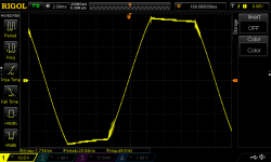
I just tested the clipping performance of my Honey Badger (just fired it up for the first time yesterday, with +/- 40 VDC rails). I have the Baker Clamp diode (BAV21) installed, but I do get some high frequency issues at 50 Hz and below. The glitches go away at higher frequencies (I tested at 500 Hz and above). Is this expected / normal behaviour?
Attachments
@mbrennwa: man, my VAS heatsink is at least twice that size.
I'll link a pic of my heatsink:
honeybadger - Imgur
Yes, i have +/- 63v rails.
These values are taken when the amp is warm, ~20mins of idle on-time.
R27 = 68r on my boards, following the v2.4 build guide.
Across R27 shows 0.565vdc.
My CCS current would be 0.565v / 68r = 0.008, so 8ma?
Other voltages that i'm aware of for reference:
Across R14 = 8.22vdc
SpkrOut to Ground = 0.000 - 0.001vdc
TP1 to TP2 = 0.030vdc
Also, from a cold start it takes about 5-10mins for the HS to get noticeably warm, about 30mins for very warm, and an hour for too hot to touch or almost too hot.
..thinking about it, i didn't notice this too hot thing until it was all together and in a closed case. When it was apart and in my garage that room is a good 15deg colder than the room its going to live in.
Since it has been open and sitting on my desk playing music it hasn't become too hot to touch, nice and toasty, but not too hot. Maybe i just need a small fan in the case?
Last edited:
- Home
- Amplifiers
- Solid State
- diyAB Amp The "Honey Badger" build thread