Very exciting, things are progressing very good! Your job is awesome, Thimios! Can't wait for you to do the same with the 4 pairs OS!
Thanks for your work!
Gaetano.
Thanks for your work!
Gaetano.

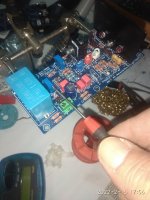
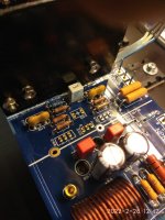
Hm,i will look closer at this latter.Not sure the trimmer will be blocked?
If you will use a very thin screwdriver you will not have a problem adjusting the deflection voltage.
Another solution is to use ,a piece of fiber glass or something similar,underside the trimer to rise this s little.
Another solution is to use ,a piece of fiber glass or something similar,underside the trimer to rise this s little.
Attachments
Last edited:
If the PCB is mounted parallel to the heatsink you may want to mount the trim pots facing the other way, so you can do adjustments from the top. Obviously, for adjustments, you will turn the trim pot in the opposite direction....
If you have a very large chassis you may use top adjust trim pots, if you like.
Many options, pick a solution that suits your needs.
If you have a very large chassis you may use top adjust trim pots, if you like.
Many options, pick a solution that suits your needs.
Sure, it is not a big deal and highlighted for the diyer regarding when installing it with other option.
We need this type of feedback and we will make a note in the BOM and Build Guide.
Hi guy's,
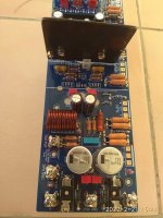
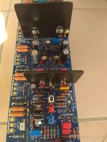
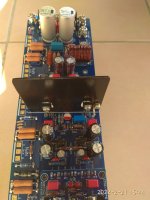
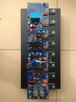
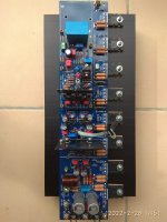
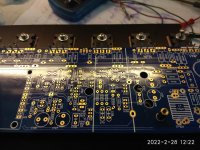
Just a quick update on Thimios's progress. He has completed the build of the amplifier PCB except for installing the output transistors.
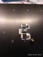
He is in the process of drill and mounting the pcb on a heatsink.
Thanks for your efforts on this project Thimios.
Just a quick update on Thimios's progress. He has completed the build of the amplifier PCB except for installing the output transistors.
He is in the process of drill and mounting the pcb on a heatsink.
Thanks for your efforts on this project Thimios.
Attachments
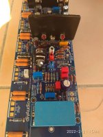
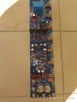
Hi Stuart, my picture above showed.
It is not standard heatsink, so how large of size should be used?
And what the purpose of screw contact on the heatsink? This flat plane heatsink does not contact to the transistors?
It is not standard heatsink, so how large of size should be used?
And what the purpose of screw contact on the heatsink? This flat plane heatsink does not contact to the transistors?
As I said its the CCS2 and VAS Heatsink and is 50mm x 30mm x 1.2mm (Minimum)Hi Stuart, my picture above showed.
It is not standard heatsink, so how large of size should be used?
You need to make it yourself. Dimension and hole locations will be shown in the comprehensive build guide currently 34 pages.
To ground the heatsink to prevent any tray parasitic capacitance from building up and affecting the transistors or surrounding components. Grounding the heatsink provides a easy path back to ground for any capacitively coupled EMI etc.And what the purpose of screw contact on the heatsink?
This depends on the transistors used whether you need an insulator pad or Kapton tape. But at the end of the day both transistors need to be electrically isolated from making contact with the Heatsink.This flat plane heatsink does not contact to the transistors?
Hi Guy's,
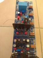
Just a update from Thimios.
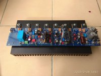
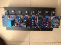
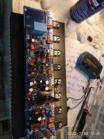
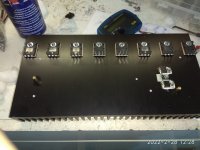
He has done a great job finishing off the assembly of the EF3-4 pair ready for testing.
Please note that the heatsink that Thimios has used is just for testing purposes. The heatsink was just one that he had on hand.
Just a update from Thimios.
He has done a great job finishing off the assembly of the EF3-4 pair ready for testing.
Please note that the heatsink that Thimios has used is just for testing purposes. The heatsink was just one that he had on hand.
Attachments
-
 IMG-20220228-WA0027(2).jpg84.2 KB · Views: 295
 -
 IMG-20220228-WA0025(4).jpg93.9 KB · Views: 289
 -
 IMG-20220228-WA0024(4).jpg98.2 KB · Views: 265
 -
 IMG-20220228-WA0026(1).jpg97.9 KB · Views: 266
 -
 IMG-20220228-WA0025(3).jpg93.9 KB · Views: 266
 -
 IMG-20220228-WA0024(3).jpg98.2 KB · Views: 235
 -
 IMG-20220228-WA0023(1).jpg115.7 KB · Views: 235
 -
 IMG-20220228-WA0022(1).jpg96.6 KB · Views: 243
 -
 IMG-20220228-WA0021(1).jpg48.9 KB · Views: 238
 -
 IMG-20220228-WA0020(1).jpg135.3 KB · Views: 236
 -
 IMG-20220228-WA0019(1).jpg81.2 KB · Views: 293
Your heatsink needs to be a minimum of 350mm long to run the EF3-4 and Ideally 400mm long. The one shown in Thimios's photos is 300mm long and is inadequate for a real build as I said in my post above.@thimios: can you tell me the length of the long side of the heatsink that you’ve used as shown in the previous post
Inadequate in terms of heat dissipation ? Probably not if your the heatsink was 300 x 300 x 75 . . . .Your heatsink needs to be a minimum of 350mm long to run the EF3-4 and Ideally 400mm long. The one shown in Thimios's photos is 300mm long and is inadequate for a real build as I said in my post above.
- Home
- Amplifiers
- Solid State
- DIYA store "Wolverine" (Son of Badger) .... suggestions ??