When taking ground referenced measurements leave the (-) black lead on ground and the (+) red lead on the measurement point, that way I can tell if it's posistive or negative.jjs:
On the left channel IPS, I get 42.2 VDC across G1 and R6 (the side towards the bottom of the schematic). On the other side of R6 (the side connected to the Base of Q6), I read 43.1 VDC.
Thoughts?
Regards.
Let's take it back one step...
On the EF3 board measure TP105 (+48V) and TP106 (-48V) referenced to ground.
Jeremy
You are in good hands, listen and follow, Jer will get you there. 😉
JT
JT

Scott, this could be really difficult to diagnose. What would make it easier for you and us trying to help you is.
1. Remove the amplifier modules from your chassis.
2. Separate the IPS and the output stage board.
3. Take some clear high resolution photos.
4. Use the build guide and check over your boards.
5. Start to test each board individually as shown in the build guide stating with the IPS board.
6. Work through one step at a time and report back with the step were things aren't correct.
This will make the whole process easier.
Good luck
Stuart

Build related problems should be posted here
https://www.diyaudio.com/community/threads/diy-class-a-b-amp-the-wolverine-build-thread.385920/
Jeremy
https://www.diyaudio.com/community/threads/diy-class-a-b-amp-the-wolverine-build-thread.385920/
Jeremy
0.000042 % THD + N at 1 kHz
Those are impressive measurements. Thank you.
Those are impressive measurements. Thank you.
Last edited:
Heyenc, this is the final step of the design process, what we designed for and it is confirmation, finally, that we, collectively, did it.See post 2006. Build thread is where these should be.
More importantly this is what the current design, BOM and build guide can deliver when any DIYer builds it.
(but yes, I am sure it will end up in the Build thread too)
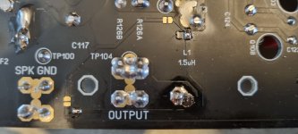
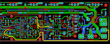
Hello everybody. Looking at the Osstriper PCB, why are the resistor and the suspended capacitor referenced in the GND of the speaker and not in the star G2? Thank you for your patience and care.
Please provide a clearer question. Maybe a photo, sketch or post number.Hello everybody. Looking at the Osstriper PCB, why are the resistor and the suspended capacitor referenced in the GND of the speaker and not in the star G2? Thank you for your patience and care.
So we can try and help you.
RLft, diodes D1 e D2 e CLft, could it not be referenced in the G2 star?Please provide a clearer question. Maybe a photo, sketch or post number.
So we can try and help you.
Attachments
Hi CLPK, we did this to separate the Signal Ground from the many and higher currents flowing in the Power Ground. The placement of those traces also avoids nearby noise sources. There are other areas where separate tracks are used, in the feedback path for example, in order to achieve the extremely low noise and distortion floor of the overall design.
I understand, is that why the negative feedback is also in parallel with the GND speaker?Hi CLPK, we did this to separate the Signal Ground from the many and higher currents flowing in the Power Ground. The placement of those traces also avoids nearby noise sources. There are other areas where separate tracks are used, in the feedback path for example, in order to achieve the extremely low noise and distortion floor of the overall design.
Hey, it's Dbl.aa
I think I want to build Honey BADGER BUT WHAT ARE THE POWER OUTPUTS(RMS)
and can it be built like mono blocks?
Thanks for help.
I have very little knowledge other than researching the last cpl years as far as building circuits . Plus I suck on computers and NEW TO USING ANY FORUMS.
So excuse me if I'm a little ruff around the edges.
I REALLY WANT MY AMP (BUILD) DIY KIT /PARTS LIST TO ORDER . ANY TIPS. WELL APPRECIATED GUYS🤠
Yes you can build mono blocks.Hey, it's Dbl.aa
I think I want to build Honey BADGER BUT WHAT ARE THE POWER OUTPUTS(RMS)
and can it be built like mono blocks?
Thanks for help.
I have very little knowledge other than researching the last cpl years as far as building circuits . Plus I suck on computers and NEW TO USING ANY FORUMS.
So excuse me if I'm a little ruff around the edges.
I REALLY WANT MY AMP (BUILD) DIY KIT /PARTS LIST TO ORDER . ANY TIPS. WELL APPRECIATED GUYS🤠
For power rating please see the images attached to the first post
Here
see the 2nd Group buy post for all the documentation you will receive once you place your order for PCB's.
Here
- Home
- Amplifiers
- Solid State
- DIYA store "Wolverine" (Son of Badger) .... suggestions ??