Guys, if some of you know about any other mid-bass driver than those I have mentioned that integrate better with a two way sealed bookshelf and the price don't exceed $80 each, please, suggest them. I mentioned the Scanspeak and the Peerless because they were in my price range. Thanks
So, I can use any 35L enclosure ?? I mean not matter how I chose theIf you can accommodate 35L it provides enough volume for the driver and gives a Butterworth maximally flat amplitude response. This should sound good.
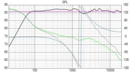
See attached simulation.
dimensions if I keep the internal volume 35L ?? And the crossover ?? Can I keep the same you suggested ?? Thanks
These are good woofers to be employed in 2 way's.
ScanSpeak Classic P21WO20
ScanSpeak Classic P21WO20 8" Woofer Poly Cone
Peerless Nomex 830869
Peerless Nomex 830869 - 8" Nomex Cone Woofer
ScanSpeak Classic P21WO20
ScanSpeak Classic P21WO20 8" Woofer Poly Cone
Peerless Nomex 830869
Peerless Nomex 830869 - 8" Nomex Cone Woofer
The dimensions will affect the baffle step response, I have assumed a 300mm wide baffle by 500mm high. However it will only mildly affect the response and the placement in the room makes as much difference. So the design will work for most shapes of cabinet.
The crossover is almost completely independent of the baffle so you shouldn't need to change it. The bass alignment is independent of the baffle shape and depends only on the volume (so long as you don't make the cabinet ridiculously long and thin). You will need some damping in the cabinet and some wadding to reduce internal reflections.
I have assumed a time delay offset of 20mm from the tweeter to the woofer which is typical and as the drivers are in Phase at the crossover you should have a good margin for this to be longer or shorter. It would be good to keep the tweeter as close the woofer as possible to minimise the time delay between the woofer and tweeter paths.
However keep in mind that this is a completely theoretical simulation from the manufacturers information. You might find you want to trim the crossover once you have the real drive units in a real cabinet. This should get you pretty close to start with and should sound really quite good as a starting point. The component are all E12 values so should be fairly easy to get hold of.
The other 8 inch drivers suggested have similar or worse off axis responses so unless you particularly prefer them for some other reason, I don't think they will improve the off axis response much. They might (or might not) have better distortion characteristics or transient response but for some reason very few suppliers provide this information.
The simulation was done in Virtuix CAD which is free and the data was traced from the datasheets with the built in trace program.(Software)
If you download a copy for yourself I am happy to send you the design files if you want to play with the crossover values, so you can see what the next size up and down of component does to the response. (Just PM me an email address to send the files too) This is very helpful if your trying to trim the response once built as even if you don't have a microphone you at least know what part of the response is likely to change and by how much.
Regards
Andrew
The dimensions will affect the baffle step response, I have assumed a 300mm wide baffle by 500mm high. However it will only mildly affect the response and the placement in the room makes as much difference. So the design will work for most shapes of cabinet.
The crossover is almost completely independent of the baffle so you shouldn't need to change it. The bass alignment is independent of the baffle shape and depends only on the volume (so long as you don't make the cabinet ridiculously long and thin). You will need some damping in the cabinet and some wadding to reduce internal reflections.
I have assumed a time delay offset of 20mm from the tweeter to the woofer which is typical and as the drivers are in Phase at the crossover you should have a good margin for this to be longer or shorter. It would be good to keep the tweeter as close the woofer as possible to minimise the time delay between the woofer and tweeter paths.
However keep in mind that this is a completely theoretical simulation from the manufacturers information. You might find you want to trim the crossover once you have the real drive units in a real cabinet. This should get you pretty close to start with and should sound really quite good as a starting point. The component are all E12 values so should be fairly easy to get hold of.
The other 8 inch drivers suggested have similar or worse off axis responses so unless you particularly prefer them for some other reason, I don't think they will improve the off axis response much. They might (or might not) have better distortion characteristics or transient response but for some reason very few suppliers provide this information.
The simulation was done in Virtuix CAD which is free and the data was traced from the datasheets with the built in trace program.(Software)
If you download a copy for yourself I am happy to send you the design files if you want to play with the crossover values, so you can see what the next size up and down of component does to the response. (Just PM me an email address to send the files too) This is very helpful if your trying to trim the response once built as even if you don't have a microphone you at least know what part of the response is likely to change and by how much.
Regards
Andrew
Thank you.! This is all I need. I will get those drivers at the beginning of the new year to begin the project. I am sending you my email in a PM.
The dimensions will affect the baffle step response, I have assumed a 300mm wide baffle by 500mm high. However it will only mildly affect the response and the placement in the room makes as much difference. So the design will work for most shapes of cabinet.
The crossover is almost completely independent of the baffle so you shouldn't need to change it. The bass alignment is independent of the baffle shape and depends only on the volume (so long as you don't make the cabinet ridiculously long and thin). You will need some damping in the cabinet and some wadding to reduce internal reflections.
I have assumed a time delay offset of 20mm from the tweeter to the woofer which is typical and as the drivers are in Phase at the crossover you should have a good margin for this to be longer or shorter. It would be good to keep the tweeter as close the woofer as possible to minimise the time delay between the woofer and tweeter paths.
However keep in mind that this is a completely theoretical simulation from the manufacturers information. You might find you want to trim the crossover once you have the real drive units in a real cabinet. This should get you pretty close to start with and should sound really quite good as a starting point. The component are all E12 values so should be fairly easy to get hold of.
The other 8 inch drivers suggested have similar or worse off axis responses so unless you particularly prefer them for some other reason, I don't think they will improve the off axis response much. They might (or might not) have better distortion characteristics or transient response but for some reason very few suppliers provide this information.
The simulation was done in Virtuix CAD which is free and the data was traced from the datasheets with the built in trace program.(Software)
If you download a copy for yourself I am happy to send you the design files if you want to play with the crossover values, so you can see what the next size up and down of component does to the response. (Just PM me an email address to send the files too) This is very helpful if your trying to trim the response once built as even if you don't have a microphone you at least know what part of the response is likely to change and by how much.
Regards
Andrew
Thanks again for your valuable help.! I need to begin with something and you gave me the starting point. If I have to change the crossovers and even the cabinet design, I will do it until I be happy with the sound.
I will do it until I be happy with the sound.
If you are happy with the sound go for even more happiness.
Although it is not always possible. Too many compromises.
If you are happy with the sound go for even more happiness.
Although it is not always possible. Too many compromises.
I am happy when my ego, vanity, hubris are satisfied.
I am working on my Peerless 830869 + SB26ADC speaker. Enclosures are soon finished and the project will move into response measurements and crossover design. It will be 20l sealed (to be used with subwoofers) thin-wall cabinet heavily damped with bitumen (2cm of bitumen per 7mm of plywood). Assuming simulations are correct, it will do nicely with ~1500Hz BW3 acoustic XO. Will make a new thread when I have something more concrete to say.
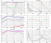
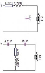
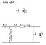
As you mentioned you were happy to go more complex on the crossover I have increased the HF crossover to a third order electrical (basically adding another capacitor) the design is still an in phase 4th order Linkwitz-Riley acoustic alignment however it has enabled me to adjust the crossover region further.
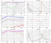
I have compromised the phase slightly to improve the power response and used the extra capacitor to enable me to improve the on axis response as well as the off axis response. If you look at the power response you can now see that the power in the room is smoother as are the off axis responses. The extra capacitor has enabled me to improve the filter roll off (You can see that the filter roll-off is lightly sharper out of band than the last design.)
This will most likely give the speaker a more forward response, as this is a region the ear is quite sensitive in. It should also be more natural sounding as the in room power response is now smoother. However it is very difficult to predict what will happen with real drive unit.
The resistances are intended to be the inductor resistance, the bass resistance doesnt affect the crossover much it just drops the sensitivity as it gets higher. However the tweeter inductor resistance adjusts the Q of the filter and so is quite important. If you cant find an inductor of the right resistance one with a lower resistace can be combined with a resitor.
Attachments
Last edited:
As you mentioned you were happy to go more complex on the crossover I have increased the HF crossover to a third order electrical (basically adding another capacitor) the design is still an in phase 4th order Linkwitz-Riley acoustic alignment however it has enabled me to adjust the crossover region further.
I have compromised the phase slightly to improve the power response and used the extra capacitor to enable me to improve the on axis response as well as the off axis response. If you look at the power response you can now see that the power in the room is smoother as are the off axis responses. The extra capacitor has enabled me to improve the filter roll off (You can see that the filter roll-off is lightly sharper out of band than the last design.)
This will most likely give the speaker a more forward response, as this is a region the ear is quite sensitive in. It should also be more natural sounding as the in room power response is now smoother. However it is very difficult to predict what will happen with real drive unit.
You did some changes to the bass driver crossover too. You increase the inductor to 1.2mH and dropped the capacitor to 33mF. What effect does this change cause?? What is the crossover frequency of this crossover ?? Thank
The crossover frequency is slightly lower arround 1800, The slightly larger inductor reduces the frequency at which energy is blocked and I have adjusted the Q of the filter with the capacitor to slight increase the frequency at which the capacitor shunts energy to the ground. Over all this reduces the crossover frequency slightly but also boosts the crossover region slightly to give a smoother response.
Reducing the crossover below the 2k recommendation for a 12dB crossover is possible because the extra capacitor cuts the power to the tweeter faster outside the pass band (as it forms a 18dB per octave filter). By going a bit lower I can reduce the use of the region of the bass driver that has poor off axis response (1kHz and up getting worse the higher you go).
Reducing the crossover below the 2k recommendation for a 12dB crossover is possible because the extra capacitor cuts the power to the tweeter faster outside the pass band (as it forms a 18dB per octave filter). By going a bit lower I can reduce the use of the region of the bass driver that has poor off axis response (1kHz and up getting worse the higher you go).
The crossover frequency is slightly lower arround 1800, The slightly larger inductor reduces the frequency at which energy is blocked and I have adjusted the Q of the filter with the capacitor to slight increase the frequency at which the capacitor shunts energy to the ground. Over all this reduces the crossover frequency slightly but also boosts the crossover region slightly to give a smoother response.
Reducing the crossover below the 2k recommendation for a 12dB crossover is possible because the extra capacitor cuts the power to the tweeter faster outside the pass band (as it forms a 18dB per octave filter). By going a bit lower I can reduce the use of the region of the bass driver that has poor off axis response (1kHz and up getting worse the higher you go).
It is clear for me now. One last question, cutting the crossover lower than 2k Hz doesn't cause the tweeter goes a little bit saturated with mid frequencies ?? My concern is I listen to rock and pop mostly at moderated to high volume. According to my view and poor knowledge, I thought it is easier for a woofer to handle mid frequencies than to allow the tweeter to handle them. This idea is thinking about mechanical and electrical limitations of both drivers. I see I may have this idea totally wrong, after reading your explanation. As you said, adding an extra capacitor you are protecting the tweeter and going lower with the woofer you are narrowing the region where the woofer is weak responding to some mid-range frecuencies. As long as the tweeter be protected and doesn't distort at high volume, this is ok for me. Thanks
Last edited:
I find this article about crossovers very informative.
General Requirements for a Crossover | Audio Undone
General Requirements for a Crossover | Audio Undone
I find this article about crossovers very informative.
General Requirements for a Crossover | Audio Undone
A good find.

C.M
This is a compromise, if you want to play really loud with these speakers then the max long term power would be improved by moving the crossover frequency up. However as you do this the off axis polar response will get worse and worse. Also woofers tend to distort in this region as the cone has stopped moving as one and breaks up with different sections of the cone moving at different time. As the cone goes more and more into cone break up they resonate and the cone starts to ring like a bell this causes energy storage and poor trasient response.
The tweeter you have chosen seems to have been designed with running at relatively low frequencies in mind, hence the 2k power bandwidth measurement. Moving it another 200Hz lower is unlikely to cause any power problems as the tweeter is quite sensitive and if you look at the filter electrical responses you can see the filter is already attenuating quite alot at the Xover frequency. Combining this with the extra order of filtering should give you the full power response. What is much more difficult to predict is how the distortion performance will behave. As you increase cone excursion on the tweeter it will distort more and the lower the frequencies you run into it will increase the excursion. I usually find for home use using as much of the range of the tweeter as possible gives a lower distortion, better transient response design which sounds better, typically better sound than running the woofer higher. The trade off is that it might not behave as well at very very high power levels, but as this design is quite sensitive anyway at about 92dB, you will get alot of sound for the input power.
Its my best guess, I can’t promise it will work well in all circumstances but I think it will give you a good compromise between sound quality, transient response, polar response, power response and distortion. If I were making this design I would go with the more complex crossover.
I will look to see if you can shift the crossover up to 2K with this design by only changing the caps (as this it is typically cheaper and easier to get hold of capacitors) which would give you the option of trying both however I think I found the phase was getting poor.
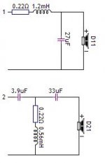
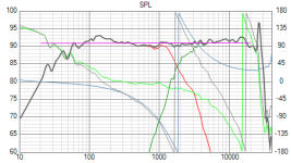
I found another sweet spot with a slightly higher crossover frequency around 2KHz and the smother HF filter means excursion in the tweeter should be reduced in the crossover region. This looks to have retained the improved off axis response and has slightly improved phase response. You will need a better inductor for this response as the required inductor resistance is lower and 33uF is a large capacitor to use in a tweeter circuit as usually you want to use a polypropylene. (the 33uf pulls the response up in the crossover region and adjust phase without it, it still works but looks more like the original filter). I am not sure the extra couple of dB headroom in the crossover region is worth it.
Attachments
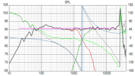
I have extended the frequency to 40kHz in the attached plots you can see there is a very significant resonance in this tweeter at 27KHz, this is common in metal dome tweeters. A music signal should not have any significant energy in this region however this resonance is so high that harmonic distortion from lower down in the frequency range could set it off.
Some people don't find this a problem at all and just perceive this as metallic sounding or are completely unaware of its affect. However some people find this extremely fatiguing and unpleasant (I am one of those).
If you find this is a problem then a HF filter should help. I have simulated a second order HF filter so you can see the effect. The attached plots show the crossover with filter and a plot without and with the filter (you can see how it attenuates the 27KHz resonance.
Attachments
- Status
- Not open for further replies.
- Home
- Loudspeakers
- Multi-Way
- DIY vs brand speaker