My hobby-listening room is in the basement of the home. Its walls are cinder blocks; which are intrinsically porous or can pass-thru air and water vapor.
I had coated the cinder blocks with an acrylic water-borne paint to minimize their shedding of concrete dust. The coated walls are still semipermeable. I can push my breath thru a sample section. This large surface membrane [coating] absorbs sound via inelastic exchange of momentum of the impinging air molecules. I had made the connection between the nature of these walls and the generally fully satisfactory sound in it.
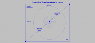
The attached schematic models the room as a still pond of water. I drop a rock in its center. Concentric waves [peaks and valleys] are generated which travel as shown towards the boundaries of the room
I hear the [70 Hz say] first because of its short arrival time. It then bounces back to travel to the other corner. The parent wave simultaneously reaches the Infinity woofer; or preferably "the Pass Shadow. The 70Hz is attenuated by ~6 dB by the Shadow and its residual bounces back to my corner.
The back and forth bouncing waves interfere with each other to create standing waves along the diagonals. I can hear [absent the Shadow] along this diagonal locations of high SPL and other silent ones. These nodes fingerpoint to standing waves.
Note the waves in the picture which bounce back and forth form the walls. What a mess? This pond has choppy waters; confusing my hearing brain; where's the sound coming from exactly? I can see the reason four Shadows in the corners are needed to restore more "quiet: to this room to better interpret and enjoy music.
Best
Anton
I had coated the cinder blocks with an acrylic water-borne paint to minimize their shedding of concrete dust. The coated walls are still semipermeable. I can push my breath thru a sample section. This large surface membrane [coating] absorbs sound via inelastic exchange of momentum of the impinging air molecules. I had made the connection between the nature of these walls and the generally fully satisfactory sound in it.
The attached schematic models the room as a still pond of water. I drop a rock in its center. Concentric waves [peaks and valleys] are generated which travel as shown towards the boundaries of the room
I hear the [70 Hz say] first because of its short arrival time. It then bounces back to travel to the other corner. The parent wave simultaneously reaches the Infinity woofer; or preferably "the Pass Shadow. The 70Hz is attenuated by ~6 dB by the Shadow and its residual bounces back to my corner.
The back and forth bouncing waves interfere with each other to create standing waves along the diagonals. I can hear [absent the Shadow] along this diagonal locations of high SPL and other silent ones. These nodes fingerpoint to standing waves.
Note the waves in the picture which bounce back and forth form the walls. What a mess? This pond has choppy waters; confusing my hearing brain; where's the sound coming from exactly? I can see the reason four Shadows in the corners are needed to restore more "quiet: to this room to better interpret and enjoy music.
Best
Anton
Attachments
Marching along..
My DIY embraces the concept and essentially copies the Pass patent. But my system has a different structural format than the Shadow; which I expect to operate in a similar manner.
My Radio Shack SPL meter reads ~a maximum 80 dB in the corner of the Infinity woofer; opposite to where I usually sit listening to a comfortable level of music.
It follows that the resultant sensitivity of the sensing Infinity woofer is a maximum 10 mVp-p. It is numerically similar to that of an Electret facing an 80 dB SPL wave.
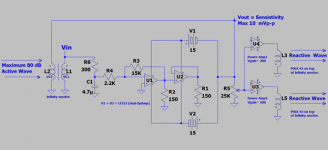
Please see the attached schematic which I'll use to explain the above.
1. The leftside of the schematic shows an 80 dB [SPL] wave pushing against the woofer cone.
2. The associated amplifier [LF353N] is a current source micro amp. It generates an output signal [Vout = Sensitivity].
3. But; unlike an Electret this Infinity woofer cone is reactive to the incident wave due to positive feedback in and around the microamp. This is desirable and means the cone continues to move inwards, and thus reduce air pressure at its surface.
4.The rightside of the schematic shows a non-phase inverting stereo power amp which accepts [Vout] to drive a pair Polk 42 bookshelf loudspeakers which sit atop the Infinity enclosure. Their woofer cones are needed.
5. Note the out-of-phase dots on the Polk 42s versus those of Infinity woofer. The simultaneouly Reactive Polk Cones must move in the same direction as the incident wave; meaning they must not confront the offending sound wave and thus raise SPL instead of attenuating it.
6. The potentiometer at the input of the power amps adjusts the resultant SPL of the Reactive Polk Cones to attenuate the incident sound wave. It enables me to adjust the overall music quality.
7. I'll post a fresh picture of these corner-sitting loudspeakers.
Best wishes
Anton
My DIY embraces the concept and essentially copies the Pass patent. But my system has a different structural format than the Shadow; which I expect to operate in a similar manner.
My Radio Shack SPL meter reads ~a maximum 80 dB in the corner of the Infinity woofer; opposite to where I usually sit listening to a comfortable level of music.
It follows that the resultant sensitivity of the sensing Infinity woofer is a maximum 10 mVp-p. It is numerically similar to that of an Electret facing an 80 dB SPL wave.
Please see the attached schematic which I'll use to explain the above.
1. The leftside of the schematic shows an 80 dB [SPL] wave pushing against the woofer cone.
2. The associated amplifier [LF353N] is a current source micro amp. It generates an output signal [Vout = Sensitivity].
3. But; unlike an Electret this Infinity woofer cone is reactive to the incident wave due to positive feedback in and around the microamp. This is desirable and means the cone continues to move inwards, and thus reduce air pressure at its surface.
4.The rightside of the schematic shows a non-phase inverting stereo power amp which accepts [Vout] to drive a pair Polk 42 bookshelf loudspeakers which sit atop the Infinity enclosure. Their woofer cones are needed.
5. Note the out-of-phase dots on the Polk 42s versus those of Infinity woofer. The simultaneouly Reactive Polk Cones must move in the same direction as the incident wave; meaning they must not confront the offending sound wave and thus raise SPL instead of attenuating it.
6. The potentiometer at the input of the power amps adjusts the resultant SPL of the Reactive Polk Cones to attenuate the incident sound wave. It enables me to adjust the overall music quality.
7. I'll post a fresh picture of these corner-sitting loudspeakers.
Best wishes
Anton
Attachments
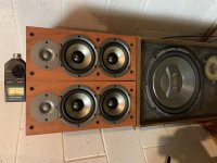
This is the DIY...
The placement symmetry of the drivers is pleasing; accidental!
I listened for an hour+ to music with this DIY device activated.
1. The potentiometer to the power amps driving the Polk 42s was set at ~9 o'clock.
2. The scope showed a maximum ~50 mVp-p at the output of each power amp. The impedance of a Polk 42 is 4 Ohms.
3. I caught the Radio Shack SPL meter registering ~ 80 dB when I took the picture. There's a specific frequency as seen on scope which does that.
4. The quality of sound at my listening corner is fully satisfactory. My hearing tells of bass attenuation; be it due to standing waves [reverberant] and/or instantaneous music. The residual audio spectrum is bright/clear, intelligible and is panoramic behind the main ADS loudspeakers.
I have other loudspeakers to put [store] in the orthogonal corner next to the right ADS speaker. This will remove more reverberant and active bass in the room to further improve the fidelity of music.
NB. I wished to upright the pic and obviously failed!
Best wishes
Anton
Attachments
A reactive microphone
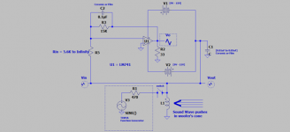
The attached schematic is the subject prototype. It shows:
1. Two independent schematics which are separated by the horizontal # divider.
2. Each amp [LF353] in its schematic is current source.
3. The upper one is" transformer-coupled" because of the DVC Infinity woofer [far left].
4.The lower one uses two series connected Polk 42 loudspeakers. It can operate solo.
5. I've stacked the 5 woofers by joining the upper and lower schematics. This is the photo in the previous post. It is configured as a massive microphone. The ensemble woofers give an equivalent [4 x 5.25 + 12] = ~33 inch equivalent driver or in this application a reactive microphone.
6. Both current source amps embody a needed positive feedback. As the soundwave pushes the woofers in unison, their resultant inward displacement is assisted or augmented by positive feedback. The woofer cones continue to move inward and thus drop the air pressure at their faces. I perceive it works. This is my meaning of a reactive microphone.
Best wishes
Anton
Attachments

Status of experiments
The current prototype has the attached schematic. It is simple and effective. It uses Positive Feedback [PF] as posted earlier. What PF level is enough? Too much appears detrimental; meaning the cone can overshoot the required remedy and is audible. The remedy is the "optimal" value of Rin [R5].
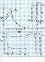
I show two attached graphs which I generated from data I collected to the right of each. They address my search for the best value for [Rin]. I use a TENMA function generator to do so.
TOP graph.
1.Vol and Vol' are relative values for output level at the woofer[L]. They are AC readings on a digital multimeter. I normalized the plot data by making the 100 Hz Vols equal to 1.
2. Vol pertains to an absent [Rin] or is equal to Infinity. Its plot is the characteristic curve of Impedance vs. Frequency for a woofer driven by a current source amp; as used here. Its graph is The "bull's-eye" data points. Resonance frequency ~47Hz.
3. Vol' pertains to Rin = 8.2K. Its graph points are the squares.
Bottom graph.
1. Graph is a scan of [Vol] as a function of Rin [gain of OpAmp] at a fixed 45 Hz which is the peak found in the above graph.
2. I used Rin = Infinity as the datum to normalize the graph points.
3. The data show that Vol began to increase for Rin equal to 39K and then took off at Rin = 10K and lower. That's [PF] in action; which keeps the cone moving in the same direction as the impinging phase of the soundwave . I use Rin = 8.2K. It gave a normalized Voltage Gain = 2.3. Other Values up to 15K are also acceptable.
4. The amp/room oscillates for Rin = 3.3K.
I'll post pics of the prototype.
Best wishes
Anton
The current prototype has the attached schematic. It is simple and effective. It uses Positive Feedback [PF] as posted earlier. What PF level is enough? Too much appears detrimental; meaning the cone can overshoot the required remedy and is audible. The remedy is the "optimal" value of Rin [R5].
I show two attached graphs which I generated from data I collected to the right of each. They address my search for the best value for [Rin]. I use a TENMA function generator to do so.
TOP graph.
1.Vol and Vol' are relative values for output level at the woofer[L]. They are AC readings on a digital multimeter. I normalized the plot data by making the 100 Hz Vols equal to 1.
2. Vol pertains to an absent [Rin] or is equal to Infinity. Its plot is the characteristic curve of Impedance vs. Frequency for a woofer driven by a current source amp; as used here. Its graph is The "bull's-eye" data points. Resonance frequency ~47Hz.
3. Vol' pertains to Rin = 8.2K. Its graph points are the squares.
Bottom graph.
1. Graph is a scan of [Vol] as a function of Rin [gain of OpAmp] at a fixed 45 Hz which is the peak found in the above graph.
2. I used Rin = Infinity as the datum to normalize the graph points.
3. The data show that Vol began to increase for Rin equal to 39K and then took off at Rin = 10K and lower. That's [PF] in action; which keeps the cone moving in the same direction as the impinging phase of the soundwave . I use Rin = 8.2K. It gave a normalized Voltage Gain = 2.3. Other Values up to 15K are also acceptable.
4. The amp/room oscillates for Rin = 3.3K.
I'll post pics of the prototype.
Best wishes
Anton
Attachments
Pics
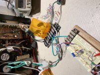
Attached is a picture of the prototype. The Radio Shack [RS] receiver on the left of the view has a hefty +/- 62V PSU.
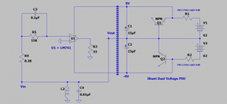
1. The attached schematic shows the complete circuit of the amp and its downsized PSU.
2. The parent RS PSU was downsized to a +/-9V shunt type which feeds LM741.
3. The TO-3 NPN bjts are connected as power Zeners. Each sits in a pill container which is vented at its top and bottom to cool.
4. The LM741 circuit is on the protoboard on the far right of the view.
Next post will show pic of the enclosed woofe [L] in schematic.
Error on schematic at the inverting poort of LM741. Defer to the schematic in previous post
Best
Anton
Attached is a picture of the prototype. The Radio Shack [RS] receiver on the left of the view has a hefty +/- 62V PSU.
1. The attached schematic shows the complete circuit of the amp and its downsized PSU.
2. The parent RS PSU was downsized to a +/-9V shunt type which feeds LM741.
3. The TO-3 NPN bjts are connected as power Zeners. Each sits in a pill container which is vented at its top and bottom to cool.
4. The LM741 circuit is on the protoboard on the far right of the view.
Next post will show pic of the enclosed woofe [L] in schematic.
Error on schematic at the inverting poort of LM741. Defer to the schematic in previous post
Best
Anton
Attachments
Last edited:
Hi Anton,
Why is Vin connected to Vout ? Why no feedback around opamp? Why 33 ohm at opamp output, is it a load?
Why is Vin connected to Vout ? Why no feedback around opamp? Why 33 ohm at opamp output, is it a load?
Hi nicotin78. I am glad to hear from you.
Roles of 33 Ohms load at the voltage source output of LM741?
1. Completes the [DC and AC] circuits with the voice coil load via ground or common. Removing it opens the circuit and nothing happens.
2. It is a common load value for headphones driven by OpAmps. It is agreeable here too.
3. The push-pull output stage of LM741 operates simultaneously as common emitter. A dual performer. Its current source output is the joined-opposed collectors of its bjts which drives the voice coil load [Vout]. The 33 Ohms grants it adequate "degeneration". Per the teachings of Mr. Pass, any amp using positive feedback is best balanced [against the expected oscillation] with a simultaneous dose of negative feedback or degeneration in this case.
Why no feedback around LM741?
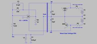
I apologize for my error in the schematic of the previous post. Attached is the proper schematic. It shows:
1. The standard negative feedback loop from the output of LM741 to its inverting input.
2. A positive feedback loop from Vout to Vin of the inverter. Though separated or named differently, the magnitude of Vout is always equal to Vin and is greater than zero where the non-inverting port sits. This state unbalances the on-chip input diff amp.
3. Negative [degeneration] feedback at the standard output of LM741 for its second current source function.
4. The PSU rails of LM741 are "decoupled" to Vload and not to common or ground. There's AC [Vout] on its voltage rails. It may be a bleed-through additional feedback to the on-chip stages so as to affect their gain.
Best wishes
Anton
Roles of 33 Ohms load at the voltage source output of LM741?
1. Completes the [DC and AC] circuits with the voice coil load via ground or common. Removing it opens the circuit and nothing happens.
2. It is a common load value for headphones driven by OpAmps. It is agreeable here too.
3. The push-pull output stage of LM741 operates simultaneously as common emitter. A dual performer. Its current source output is the joined-opposed collectors of its bjts which drives the voice coil load [Vout]. The 33 Ohms grants it adequate "degeneration". Per the teachings of Mr. Pass, any amp using positive feedback is best balanced [against the expected oscillation] with a simultaneous dose of negative feedback or degeneration in this case.
Why no feedback around LM741?
I apologize for my error in the schematic of the previous post. Attached is the proper schematic. It shows:
1. The standard negative feedback loop from the output of LM741 to its inverting input.
2. A positive feedback loop from Vout to Vin of the inverter. Though separated or named differently, the magnitude of Vout is always equal to Vin and is greater than zero where the non-inverting port sits. This state unbalances the on-chip input diff amp.
3. Negative [degeneration] feedback at the standard output of LM741 for its second current source function.
4. The PSU rails of LM741 are "decoupled" to Vload and not to common or ground. There's AC [Vout] on its voltage rails. It may be a bleed-through additional feedback to the on-chip stages so as to affect their gain.
Best wishes
Anton
Attachments
Any simpler?
Please see posts #19 and onward for pictures/explanations of the loudspeaker I used to generate the recent data and graphs.
1. It has a 10 inch dual voice coil [DVC] woofer.
2. DVCs are connected in //.
3. It sits behind my seating corner. I don't hear it; but I hear its influence in clarity as it works with other in-room absorbers.
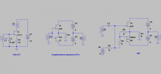
I thought of several DVC-style applications as I answered nicotin78's post. Please see the attached schematic:
1. The Solo FET at the the left of the view. Any simpler? I assembled it and it behaves. Drain current flows through DVC2. May remind of H2 by Mr. Pass.
2. The middle Complementary FETs option removes current flow through DVC2. It may idle at +/-15 mA.
3. DEF [simplified] for more power than option 2 to drive the transformer [VC1-VC2] which may be inefficient. Still, DEF may be low power.
Best wishes
Anton
Next post will show pic of the enclosed woofer [L2] in schematic.
Please see posts #19 and onward for pictures/explanations of the loudspeaker I used to generate the recent data and graphs.
1. It has a 10 inch dual voice coil [DVC] woofer.
2. DVCs are connected in //.
3. It sits behind my seating corner. I don't hear it; but I hear its influence in clarity as it works with other in-room absorbers.
I thought of several DVC-style applications as I answered nicotin78's post. Please see the attached schematic:
1. The Solo FET at the the left of the view. Any simpler? I assembled it and it behaves. Drain current flows through DVC2. May remind of H2 by Mr. Pass.
2. The middle Complementary FETs option removes current flow through DVC2. It may idle at +/-15 mA.
3. DEF [simplified] for more power than option 2 to drive the transformer [VC1-VC2] which may be inefficient. Still, DEF may be low power.
Best wishes
Anton
Attachments
Duality to sing and listen
The attached simplified schematic is for the subject prototype system. It sounds great.
I've recently posted similar schematics of low power prototypes whereby the non-inverting input of the power amp is grounded. Such a system simultaneously "listens" [microphone] and speaks quietly as a loudspeaker to attenuate the impinging sound on its cone. It is a "muted" listener.
Now, the non-inverting input of the power amp is fed a music signal from a CD player This system sings loud and clear, and still retains the aforementioned abilty. It is now a vocal listener; the ideal duality in operation and performance.
Please note that I have not violated the "rules" I put forth for operating these systems.
1. The microphone/speaker is a full-range [FR] driver which is part of a Karlson. It is 50 years old and sounds great. It is driven by a current source amp as already explained.
2.The system has 2 feedback loops to the inverting input of the power amp
2a. The standard NFB from the output of the amp. It is enabled by the 18K and 1K resistors.
2b. A postive feedback loop from the [FR] loudspeaker to the inverting input of the power amp. I've enclosed its components in a dashed rectangle. Note that the fedback signal is not bandwidth limilted.
3. A third NFB loop is for the power ouput stage which has the dual function of a voltage and current source amps. The 8 Ohms degeneration resistor is it. It also controls the current gain of this stage which is needed for stability against oscillation.
In operation, the cone of the driver simultaneously emits and receives reflected music. Its voice coil sums them for recycle.
I will post added no-big-deal details about the power amp.
Best wishes
Anton
Attachments

Follow up
The attached schematic of the prototype amp shows/adds details to the equivalent one in the previous post. It still has this thread's core DIY requirement. Please note its key features:
1. It is generic or classical. Can be otherwise.
2. The OpAmp models the 3 standard stages of: Input Differential amp followed by the Last Voltage amp [LVA] and followed by the Current Driver of the output stage. Can be an OpAmp. It has and must have an independent PSU shown as +/-15V.
3. The complementary symmetry BJT power output stage has and must have its independent PSU shown as +/-20V. It has two correlated power outputs which drive the independent Loads # 1 and #2. Correlated means the same output current flows thru both loads which is the property under focus.
I'll elaborate in a follow up post on the two loads to the power amp and posible sonic value.
Best
Anton
Attachments
If I understand it correctly, are you implementing this: https://www.diyaudio.com/forums/multi-way/20037-simple-mfb-woofer-project-4.html#post358265 ?
Thanks for the interesting circuit. It is worthy of added study to understand fully. Is my application useable for motional feedback? I do not know the answer; but will pursue it.
If I understand it correctly, are you implementing this: https://www.diyaudio.com/forums/multi-way/20037-simple-mfb-woofer-project-4.html#post358265 ?
Hello nicotin78.
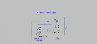
The attached schematic [solo FET] has appeared in post#129 [far left] as the simplest design to possibly manage standing waves. I've added to its gate an external 100 Hz signal [Vin] from a TENMA oscillator.
The woofer sang softly. It has experienced both motion and positive feedback. May or not be interpreted as "motional feedback".
Best
Anton
Attachments
Deviating from the status quo
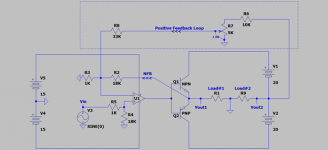
The attached schematic is for the amp understudy. It's operation deviates from the standard course as a DIY tool to explore and seek other possibilities for the listening experience. May see it as a different frontier or approach!
The amp
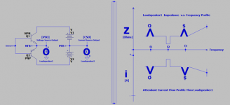
1. It has two power outputs; which are its signature for straying off the standard practice. The classical "voltage source" [VSO] drives Loudspeaker1 [R]. The additional "current source ouput" [CSO] drives Loudspeaker2 [L]. One sole current flows thru the two loudspeakers. Note the phase dot [*] imprinted on each loudspeaker.
2. [VSO] allows for global negative feedback [NFB]. [CSO] enables global positive feedback [PFB]. The two FBs give this deviant amp its characteristics.
3. The loudspeakers R and L are inherently twins in both design and performance. They are situated in my room in a standard stereo arrangement. They are the best "loads" to this deviant amp. The amp is stable against oscillation and the loudspeakers are unusually quiet.
4. The graphs to the rightside of the triple vertical lines show:
4a. The top one is a hypothetical Impedance versus Frequency curve of Loudspeaker1.
4b. The bottom one is the resultant Current Flow [v.s. frequency] in Loudspeaker1. It is an inverted mirror image of the impedance graph per Ohm's Law.
The operational result is:
Load current from [VSO] gives Loudspeaker1 [R] a pristine performance. This same load current also flows thru Loudspeaker2 [L] which has an identical impedance v.s frequency load. The attendant performance of Loudspeaker2 becomes identical to that of Loudspeaker1. This deviant amp enables another twin performer. Essentially, the [R] load equalized the current flowing thru it so as to properly drive the twin [L]. No need to modify the crossover network in the [L] load; just because it is driven by a current source instead of a voltage source output. Please see the informative articles by Mr. Pass on this subject of current/voltage source drives on his FirstWatt website.
This is a Mono system . It used one input channel [R or L] from the CD player's Vout source. Its music sounds clear, pristine, fills the room and is fullfilling. The outputs [CSO and VSO] can be reversed to the loudspeakers.
The previous posts showed that the [L] loudspeaker in this deviant amp had a special attribute [listens and speaks], and thus can absorb sound energy in addition to emitting it.
Next post will talk about adding a second deviant amp channel.
Best
Anton
The attached schematic is for the amp understudy. It's operation deviates from the standard course as a DIY tool to explore and seek other possibilities for the listening experience. May see it as a different frontier or approach!
The amp
1. It has two power outputs; which are its signature for straying off the standard practice. The classical "voltage source" [VSO] drives Loudspeaker1 [R]. The additional "current source ouput" [CSO] drives Loudspeaker2 [L]. One sole current flows thru the two loudspeakers. Note the phase dot [*] imprinted on each loudspeaker.
2. [VSO] allows for global negative feedback [NFB]. [CSO] enables global positive feedback [PFB]. The two FBs give this deviant amp its characteristics.
3. The loudspeakers R and L are inherently twins in both design and performance. They are situated in my room in a standard stereo arrangement. They are the best "loads" to this deviant amp. The amp is stable against oscillation and the loudspeakers are unusually quiet.
4. The graphs to the rightside of the triple vertical lines show:
4a. The top one is a hypothetical Impedance versus Frequency curve of Loudspeaker1.
4b. The bottom one is the resultant Current Flow [v.s. frequency] in Loudspeaker1. It is an inverted mirror image of the impedance graph per Ohm's Law.
The operational result is:
Load current from [VSO] gives Loudspeaker1 [R] a pristine performance. This same load current also flows thru Loudspeaker2 [L] which has an identical impedance v.s frequency load. The attendant performance of Loudspeaker2 becomes identical to that of Loudspeaker1. This deviant amp enables another twin performer. Essentially, the [R] load equalized the current flowing thru it so as to properly drive the twin [L]. No need to modify the crossover network in the [L] load; just because it is driven by a current source instead of a voltage source output. Please see the informative articles by Mr. Pass on this subject of current/voltage source drives on his FirstWatt website.
This is a Mono system . It used one input channel [R or L] from the CD player's Vout source. Its music sounds clear, pristine, fills the room and is fullfilling. The outputs [CSO and VSO] can be reversed to the loudspeakers.
The previous posts showed that the [L] loudspeaker in this deviant amp had a special attribute [listens and speaks], and thus can absorb sound energy in addition to emitting it.
Next post will talk about adding a second deviant amp channel.
Best
Anton
Attachments
I have noticed a few of us may qualify for senior discounts. Might one application of this be a small device to null any noise from any medical devices like an oxygen concentrator we might have ?
Thanks woody for your note, and for keeping up with my wordy posts. Interesting idea among others that work much better; like ear plugs for absolute peace and quiet.
The loudspeaker driven by [CSO] is and/or like a seismic detector. Its body [enclosure walls] couples vibration to its voice coils. Unproven; maybe reactive and thus attenuates vibrations in a wall of another enclosed speaker.
Best wishes
Anton
The loudspeaker driven by [CSO] is and/or like a seismic detector. Its body [enclosure walls] couples vibration to its voice coils. Unproven; maybe reactive and thus attenuates vibrations in a wall of another enclosed speaker.
Best wishes
Anton
What to do with the Deviant Power Amp?
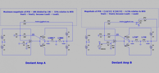
There are several applications for the Deviant Power Amp [DPA]. The attached schematic shows two independent [DPAs] which can be used as follows by driving two sets of the pictured independent loudspeakers:
Leftside DPA
1. It shows a maximum 55% positive feedback [PFB] relative to that of NFB. The system oscillated with higher values of PFB injections.
2. Two ADS L300C [the two way in pic] load this DPA's two power outputs. Please note that I labelled the one driven by the voltage source output [VSO] as L300C* for the purpose to follow.
3. Vin at the non-inverting input is zero; meaning no granted signal from the source CD player.
Rightside DPA
1. It shows ~ 7% PFB injection relative to that of NFB.
2. Please note the star labelled load "L730*" [three way in pic] to denote it being driven by the VSO of DPA.
3. Vin at the non-inverting input of the right side DPA is the signal identified as Right from the CD player source [could be L instead].
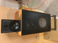
The pictured loudspeakers. Please rotate right to floor stand.
1. This loudspeaker combination is to my rightside listening position. It shows L730* [driven by voltage source] atop which is L300C [driven by current source].
2. Another loudspeaker combination like it is to my leftside listening position. Not shown it is L730 [driven by current source] atop which is L300C* [driven by voltage source].
3. The two combination sets are oriented in a typical "stereo" arrangements.
Operation
1. This is a mono listening experience from the L730 loudspeakers. There's no lefstside to rightside imaging. My brain misses this behaviour.
2. L300C atop L730* on my listening rightside is a microphone and a loudspeaker; as I've explained in past posts. It listens for the music at location and speaks [softly] while its twin [L300C*] on my listening leftside speaks [softly].
3. L730 on my listening leftside speaks and listens as explained earlier. It samples the net sound pressure to generate PFB which impacts its performance and also the performance of its twin L730*.
4. The above may suggest or is "crossstalk". A matrix of sorts.
Another application
1. The leftside DPA's PFB was made equal to that of the rightside DPA [~7%].
2. The leftside DPA was offered the Left Vin signal of the CD player instead of none.
3. The resultant "acoustic summation" of both music signal channels is still Mono. But the system embodies the other alleged acoustic benefits to listen and and speak.
Talk about deviating from the listening status quo!
Best wishes
Anton
There are several applications for the Deviant Power Amp [DPA]. The attached schematic shows two independent [DPAs] which can be used as follows by driving two sets of the pictured independent loudspeakers:
Leftside DPA
1. It shows a maximum 55% positive feedback [PFB] relative to that of NFB. The system oscillated with higher values of PFB injections.
2. Two ADS L300C [the two way in pic] load this DPA's two power outputs. Please note that I labelled the one driven by the voltage source output [VSO] as L300C* for the purpose to follow.
3. Vin at the non-inverting input is zero; meaning no granted signal from the source CD player.
Rightside DPA
1. It shows ~ 7% PFB injection relative to that of NFB.
2. Please note the star labelled load "L730*" [three way in pic] to denote it being driven by the VSO of DPA.
3. Vin at the non-inverting input of the right side DPA is the signal identified as Right from the CD player source [could be L instead].
The pictured loudspeakers. Please rotate right to floor stand.
1. This loudspeaker combination is to my rightside listening position. It shows L730* [driven by voltage source] atop which is L300C [driven by current source].
2. Another loudspeaker combination like it is to my leftside listening position. Not shown it is L730 [driven by current source] atop which is L300C* [driven by voltage source].
3. The two combination sets are oriented in a typical "stereo" arrangements.
Operation
1. This is a mono listening experience from the L730 loudspeakers. There's no lefstside to rightside imaging. My brain misses this behaviour.
2. L300C atop L730* on my listening rightside is a microphone and a loudspeaker; as I've explained in past posts. It listens for the music at location and speaks [softly] while its twin [L300C*] on my listening leftside speaks [softly].
3. L730 on my listening leftside speaks and listens as explained earlier. It samples the net sound pressure to generate PFB which impacts its performance and also the performance of its twin L730*.
4. The above may suggest or is "crossstalk". A matrix of sorts.
Another application
1. The leftside DPA's PFB was made equal to that of the rightside DPA [~7%].
2. The leftside DPA was offered the Left Vin signal of the CD player instead of none.
3. The resultant "acoustic summation" of both music signal channels is still Mono. But the system embodies the other alleged acoustic benefits to listen and and speak.
Talk about deviating from the listening status quo!
Best wishes
Anton
Attachments
Restoring stereo imaging with a bonus impact
The attached schematic shows a simplified prototype stereo system:
1. A left and right Deviant Power Amp [DPA]. The status quo Stereo Imaging is restored; by driving the ADS L730 louspeakers at the DPA's Voltage Source Outputs [VSO]
2. The Current Source Outputs [at PFB node] are loaded by the 2 voice coils of an Infinity woofer; to complete DC and AC via common. The 47uF cap across each voice coil suppessed loud whisteling.
3. Three woofer connections are possible which give this performance:
3a. Seismic Impact A>B>>C Connection A is earthquaky! The Infinity and the L730 woofers operate in phase. Connection B allows the Infinity woofer to subtract bass [relatively] from the L730 woofers because of its room antiphase connection.
3b. Cone Excursion A=B>>C
3c. Balanced spectrum C>>B>A [retro 3a]
4. A substantial Postive Feedback [PFB=0.25 NFB] was used.
The enclosed woofer was put in the corner which is at the end of the floor diagonal to my listening rightside or the R loudspeaker. Sound pressue at its cone is a sum of its output and that of returning standing waves. This woofer growls and listens.
I like woofer connection C best for its balanced audio spectrum performance. Common mode signals are mostly cancelled therein [less bassy] by its antiphase coil connections. This maximizes the magnitude signal from standing waves relative to its depressed output.
Best
Anton
Attachments

- Home
- Amplifiers
- Pass Labs
- DIY the device of US Patent 4,899,387