Hi yentzee. Your post suggests that you wish to assemble the patented circuit taught by Mr. Pass. Great idea because it works and is straightforward to implement.
btw, another older thread exists in DIYaudio regarding this Pass patent. It discussed at great length the practical device. I hope that you can find it.
Best
Anton
btw, another older thread exists in DIYaudio regarding this Pass patent. It discussed at great length the practical device. I hope that you can find it.
Best
Anton
Hi Anton, thanks for your answer. Yes I would love to build one or maybe two of them. Setting up a dba at my studio at the moment but sucking the bass away than cancelling with phase is way better as a dba stops working when objects stand in the way.
I will have a look for the thread.
As I am not good with electronics I wanted to ask whether the circuit can be built like this but use any amp ((cheap class D) and a mic instead of a double coiled chassis?
I would start straight away. I think you dont even have to etch a pcb as there are just a couple of parts used.
Have a good day.
Kind regards from Hamburg,
Jens
Managing Bass Energy in Listening Room. Part 1.
This application differs from that described by Mr. Pass. But; it removes bass energy from the listening room. This bass energy is from reverberant standing waves and music material. Please see the following background references:
1. DEF Amp thread posts #245, #284 and #294. They show the genesis of the attached prototype schematic.
2. Different headphone amps thread posts #33 and #34. The Spice models show that the output current originates from U1 [Right side OpAmp] only and not from the signal generator on the left.
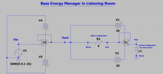
The attached schematic is simplified for one channel. Please note:
1. The R and L loudspeakers of a stereo system are key components.
2. A bookshelf loudspeaker senses bass enegy in a corner of the listening room. It is a second key part of the system. Its output signal [after lo-pass'ng; not shown] feeds the non-inverting input of power amp U1.
3. U1 is a simple DIY power amp. I show it as a buffer. It actually has feedback elements and a voltage gain 0f ~19.
3a. I have access to U1's dual rail PSU. Specifically, the center tap junction of the power transformer which is now Vout .
4. U2 is a power amp. I show it as a buffer for clarity. It is a commercial unit which has a known or not voltage gain. It plays principal roles:
4a. Its Vout is the voltage signal generator to U1 power amp.
4b. Vout is a bootstrap junction. U2 monitors the performance of U1 and corrects it as needed.
4c. Its contribution to the load current flow is trivial and is correctional only.
This system has 2 important states:
1. Useful because it removes bass energy. The phase relationship of the main and sense loudspeakers must be as shown in the schematic.
2. Useless; because its adds bass energy to the room. It further causes loud room oscillations like howling and buzzing. This state is achieved by reversing the phase of the main loudspeaker relative to the sense or the other way.
to be continued..
Best
Anton
This application differs from that described by Mr. Pass. But; it removes bass energy from the listening room. This bass energy is from reverberant standing waves and music material. Please see the following background references:
1. DEF Amp thread posts #245, #284 and #294. They show the genesis of the attached prototype schematic.
2. Different headphone amps thread posts #33 and #34. The Spice models show that the output current originates from U1 [Right side OpAmp] only and not from the signal generator on the left.
The attached schematic is simplified for one channel. Please note:
1. The R and L loudspeakers of a stereo system are key components.
2. A bookshelf loudspeaker senses bass enegy in a corner of the listening room. It is a second key part of the system. Its output signal [after lo-pass'ng; not shown] feeds the non-inverting input of power amp U1.
3. U1 is a simple DIY power amp. I show it as a buffer. It actually has feedback elements and a voltage gain 0f ~19.
3a. I have access to U1's dual rail PSU. Specifically, the center tap junction of the power transformer which is now Vout .
4. U2 is a power amp. I show it as a buffer for clarity. It is a commercial unit which has a known or not voltage gain. It plays principal roles:
4a. Its Vout is the voltage signal generator to U1 power amp.
4b. Vout is a bootstrap junction. U2 monitors the performance of U1 and corrects it as needed.
4c. Its contribution to the load current flow is trivial and is correctional only.
This system has 2 important states:
1. Useful because it removes bass energy. The phase relationship of the main and sense loudspeakers must be as shown in the schematic.
2. Useless; because its adds bass energy to the room. It further causes loud room oscillations like howling and buzzing. This state is achieved by reversing the phase of the main loudspeaker relative to the sense or the other way.
to be continued..
Best
Anton
Attachments
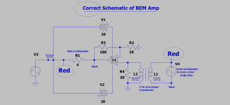
I made a mistake in previous schematic; sorry! Part 2.
The correct schematic is attached. It shows the proper phase relationship of the two loudspeakers which remove bass energy from the room. Note the encircled Red speaker polarity indicator.
BEM is short for Bass Energy Manager.
A Polk 45B bookshelf speaker is the bass energy sensor. It is 2-way and has a vent in its back which faces the room corner. Its drivers face the center of the room.
U1 is a DIY Class AB power amp. The music voltage from Polk 45B passes through a 5VA iron power transformer which works as a low-pass filter. The scope shows ~0.4 Vac [p-p] at the power output [Black] of U1 during music play; mostly bass signals.
The signal generator [V3] is a simple model for the input power amp in the previous schematic. It is predominantly a voltage signal generator. I use a Threshold S/150 or a 10W Sony mini amp in my experiments.
to be continued.
Best
Anton
Attachments
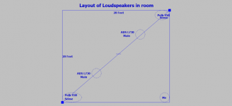
Layout of loudspeakers in listening room [Part3].
The attachment shows the positions of the loudspeakers in the room.
I sit in the corner. It is now the best room location [imho] to listen to music and to simultaneously critique its low bass subjective quality.
Best
Anton
The attachment shows the positions of the loudspeakers in the room.
I sit in the corner. It is now the best room location [imho] to listen to music and to simultaneously critique its low bass subjective quality.
Best
Anton
Attachments
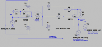
Active bass cut or bass boost or none.
The attached schematic exemplifies the status of my experiments. I use Sallen-Key low pass filters [SKlp] instead of loudspeakers in the room corners; so as to sense and manage bass energy. The action is at the non-inverting port of U1. The reference performance of this system is to ground this port; which generates a resultant baseline value for the current flowing thru the 32 Ohm load.
Please run the LTSpice model as shown.
1. The Inverted SKlp signal at the non inverting port of U1 is 180 degrees out of phase with the input music signal. It is also attenuated [arbitrary] to 0.1X the input music signal.
1a. It gives a bass boost at 100 Hz. The indicator is an increased value of the current passing thru the load relative to the baseline. Readily heard at the listening spot in the room corner.
2. The SKlp signal generator which is in phase with the input music signal is next modeled in LTSpice
2a. It gives a bass cut at 100Hz; as evidenced by a lower current value flowing thru the load than baseline. This active bass cut is readily heard in the listening corner.
I listen to all three variables; none, cut or boost. Bass cut prevents the main loudspeakers from expressing the full bass potential in the input music signal. It does not add bass. It also does not not remove bass as I had originally thought.
Why practice dymamic bass cut? My hypothesis is to attenuate the amplitude of standing waves. Thus, an improved clarity in the residual audio output emerges!
Best
Anton
Attachments
Analyses...
The left attached figure shows my hypothetical litening room which is fitted with 4 Pass structures described in his patent. Please note my seating spot which corresponds to a distance 4 feet from the structure.
I switch gears and show in the right-side attached figure my analysis of Fig.-5 in the Pass patent. I have hand-written calculations above and below it.
For the sake of discussion, I view the performance [plots A and B] an acoustic transfer function like that of a first order High Pass Filter with a slope of -6dB at an assumed F3 =200 Hz.
As music plays in this room, my ears at the 4-foot location interpret it as bass-shy; despite the ADS loudspeakers projecting full bandwidth audio.
But suppose the ADS loudspeakers instead project to the corner listening spot in my actual room a high-pass audio function like the underlined above.
My [bass-cut] experiments as told in the previous post say my ears get a bass-shy response at location. And this is my objective to manage bass in my listening room.
Best
Anton
Attachments

My post #41 in the thread "Ncore design refinement" by kazap in the Class D Forum shows using Hypex UcD180LP in an active bass cut approach.
The two attachements in this thread show:
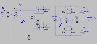
a. A redo schematic of that in post #41 above. Focus on the capacitors [500UF//0.2uF] per PSU rail which are on the Hypex PCB.
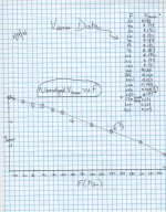
b. A plot of Vsense versus F[Hz]. Focus on how I generated Vsense [encircled] across [0.2 Ohm] at the center node of the the 2 Main PSUs.
Please note my additional explanations.
1. The on-the-PCB capacitors [500 uF//0.2uF] and the power output MOSFETs generate the Vsense graph. It [sine waves] looks like that of a low pass filter.
2. Input signal Vin from the headphone output of a CD player and Vsense are differenced in OpAmp U1 [OPA134PA]. U1 is specifically subtracting the Vsense low frequency signals from the broadband Vin signal to get an active/dynamic bass cut.
I assess music quality in my corner listening spot. I hear superb broad band audio and clear bass.
Best
Anton
The two attachements in this thread show:
a. A redo schematic of that in post #41 above. Focus on the capacitors [500UF//0.2uF] per PSU rail which are on the Hypex PCB.
b. A plot of Vsense versus F[Hz]. Focus on how I generated Vsense [encircled] across [0.2 Ohm] at the center node of the the 2 Main PSUs.
Please note my additional explanations.
1. The on-the-PCB capacitors [500 uF//0.2uF] and the power output MOSFETs generate the Vsense graph. It [sine waves] looks like that of a low pass filter.
2. Input signal Vin from the headphone output of a CD player and Vsense are differenced in OpAmp U1 [OPA134PA]. U1 is specifically subtracting the Vsense low frequency signals from the broadband Vin signal to get an active/dynamic bass cut.
I assess music quality in my corner listening spot. I hear superb broad band audio and clear bass.
Best
Anton
Attachments
simulation of active bass trap using dual coil woofer
I'm trying to simulate an active bass trap using a dual coil woofer.
I'm really not confident about the simulation ... could someone review it ?
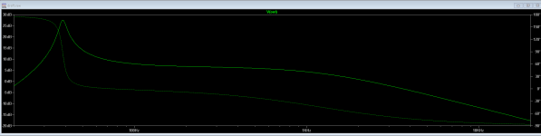
Simulation says it is highly effective up to several hundreds hertz :
Am I missing something?
I'm trying to simulate an active bass trap using a dual coil woofer.
I'm really not confident about the simulation ... could someone review it ?
Simulation says it is highly effective up to several hundreds hertz :
- Second attachement shows pressure response when the power amp is disconnected from terminal2 (bass trap inactive).
- third shows pressure response when connected (bass trap active)
Am I missing something?
Attachments

Microphone-Loudspeaker with Positive Feedback
Hi nicotin 78.
Thanks for your post. I am afraid that your work is highy advanced for me to comment on.
But; please consider simulating the following approach should you see fit; a possible collaboration!
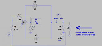
The attached schematic shows a woofer which is simultaneously a microphone and a speaker. Here's how it works:
1. A sound wave pushes the cone inward. This movig coil microphone generates an electrical signal shown as [Vin]. Note its relative phase.
1a. This microphone sees a high input impedance because it is facing the output node of a current source amp [CSA]. The signal [Vin] would otherwise be shunted had I used an interfacing voltage source amp [VSA] instead.
2. [Vin] is low-passed [150 Ohm/4.7uF] and sent to the inverting input of LF356N OpAmp of voltage gain ~3.
2a. The voltage source output of LF356N is loaded with a 33 Ohm resistor. This is a must becauses its complementary power output BJTs conduct this current and operate in the common emitter mode. This duality gives a simulataneous [CSA] with an output [Vout] which is the desired in phase with [Vin].
3. Positive Feedback asks the cone in real time to continue moving in the same inward direction [suck-it -in] which drops air pressure at the interface; and is the objective..
There's more to add..
Best
Anton
Hi nicotin 78.
Thanks for your post. I am afraid that your work is highy advanced for me to comment on.
But; please consider simulating the following approach should you see fit; a possible collaboration!
The attached schematic shows a woofer which is simultaneously a microphone and a speaker. Here's how it works:
1. A sound wave pushes the cone inward. This movig coil microphone generates an electrical signal shown as [Vin]. Note its relative phase.
1a. This microphone sees a high input impedance because it is facing the output node of a current source amp [CSA]. The signal [Vin] would otherwise be shunted had I used an interfacing voltage source amp [VSA] instead.
2. [Vin] is low-passed [150 Ohm/4.7uF] and sent to the inverting input of LF356N OpAmp of voltage gain ~3.
2a. The voltage source output of LF356N is loaded with a 33 Ohm resistor. This is a must becauses its complementary power output BJTs conduct this current and operate in the common emitter mode. This duality gives a simulataneous [CSA] with an output [Vout] which is the desired in phase with [Vin].
3. Positive Feedback asks the cone in real time to continue moving in the same inward direction [suck-it -in] which drops air pressure at the interface; and is the objective..
There's more to add..
Best
Anton
Attachments
I'm trying to simulate an active bass trap using a dual coil woofer.
I'm really not confident about the simulation ... could someone review it ?
Simulation says it is highly effective up to several hundreds hertz :
- Second attachement shows pressure response when the power amp is disconnected from terminal2 (bass trap inactive).
- third shows pressure response when connected (bass trap active)
Am I missing something?
Hello nicotin78,
I admire your proficiency in SPICE and electronics. Wao!
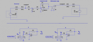
I simplified your electrical circuit for my subjective analysis [gladly]. It is shown in the attached schematic. Please note:
1. Your base electrical circuit is above the dotted line.
2. Schematic A below the line is a simplified one. The shown phase of the voice coils is a problem.
3. Schematic B is a viable solution for your continued simulations. I reversed the phase [leads] of one voice coil relative to the other. Here is how it works:
3a.The incident sound wave pushes-in the cone of the woofer. Identical [Vin] signals are generated. [Vin] at VC1 which feeds the OpAmp's inverting input survives while that instantaneously generated at VC2 is shunted by the low output impedance of the amp.
3b. The amp inverts the phase of [Vin] and amplifies it to give [Vout].
3c. Although the resultant phases of Vin and Vout appear [visually] to be out of phase, they are in phase; because of the limited transformer action which does another phase reversal. This is positive feedback! It augments the amplitude of [Vin] of VC1. Thusly, the cone continues to move in the same direction as the incident wave which is the objective to absorb it.B]
3d. This circuit is acoustically and electrically commensurate. It does not embody any violations.
May I suggest:
1. Simplify schematic by using the OpAmp only with a low voltage gain; up to five if the circuit allows it. The voltage gain of your ideal power amp maybe high [20X?], and will cause oscillation which discourages simulation.
2. Idealize the voice coils as a transformer. Although Mr. Pass had noted in a past post that it is a poor one.
Best
Anton
Attachments
Hello nicotin78 and all,
Schematic B from the previous post was prototyped. It is attached and shows the actual circuit values. It works. Please note:
1. The amp oscillated for voltage gains greater than -2.
2. It oscilated for a voltage gain = -2 when VC2 was directly connected to the output of either OpAmp. Damping factor suffered a bit.
3. Vin is low-passed. Mr. Pass did advise in a past post to band-pass it instead.
It works means the scope showed upwards of 40 mVp-p signals at the [AUX out] low pass-sense point.
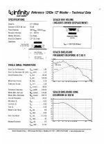
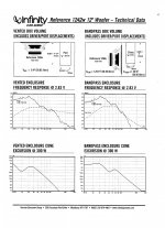
This boxed Infinity woofer may not be "ideal". Stiff suspension/rubber surround! imho one is needed which has a "more" compliant suspension to generate higher values of Vin which I had not been able to attain.
The Thiele-Small parameters for this subwoofer are attached. Good for actual simulations.
I 'll discuss the value of the [Aux Out] signal...
Best
Anton
Schematic B from the previous post was prototyped. It is attached and shows the actual circuit values. It works. Please note:
1. The amp oscillated for voltage gains greater than -2.
2. It oscilated for a voltage gain = -2 when VC2 was directly connected to the output of either OpAmp. Damping factor suffered a bit.
3. Vin is low-passed. Mr. Pass did advise in a past post to band-pass it instead.
It works means the scope showed upwards of 40 mVp-p signals at the [AUX out] low pass-sense point.
This boxed Infinity woofer may not be "ideal". Stiff suspension/rubber surround! imho one is needed which has a "more" compliant suspension to generate higher values of Vin which I had not been able to attain.
The Thiele-Small parameters for this subwoofer are attached. Good for actual simulations.
I 'll discuss the value of the [Aux Out] signal...
Best
Anton
Attachments

Hello Anton,
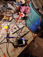
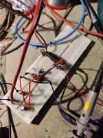
Finally I got something working, I use an electret mic, because using a dual voice coil woofer would require a too big box volume to be efficient in low frequencies.
The system is stable if not too much loop gain, increasing too much the gain, it starts oscillating at about 840hz.
Otherwise, I can see about 1Vpp when I talk/blow near the mic...
The power amp is a class D TDA7498, it introduces maybe some phase shift... I have to check ... I the mean time I ordered some class AB TDA2050 chip amps....
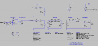
The 'control circuit' is based on https://www.ti.com/lit/ug/tidu765/tidu765.pdf?ts=1613556723420 , I just adapted C2 in order to have low pass cutoff frequency at about 100Hz.
Finally I got something working, I use an electret mic, because using a dual voice coil woofer would require a too big box volume to be efficient in low frequencies.
The system is stable if not too much loop gain, increasing too much the gain, it starts oscillating at about 840hz.
Otherwise, I can see about 1Vpp when I talk/blow near the mic...
The power amp is a class D TDA7498, it introduces maybe some phase shift... I have to check ... I the mean time I ordered some class AB TDA2050 chip amps....
The 'control circuit' is based on https://www.ti.com/lit/ug/tidu765/tidu765.pdf?ts=1613556723420 , I just adapted C2 in order to have low pass cutoff frequency at about 100Hz.
Attachments
Successful experiment
Hello nicotin78,
Thanks for your post, its pictures and TI link.
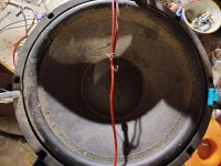
Interesting photo of the woofer in a bucket enclosure; of known volume and probably stuffed.
I look forward to your ongoing simulations-prototyping experiments.
Best
Anton
Hello nicotin78,
Thanks for your post, its pictures and TI link.
Interesting photo of the woofer in a bucket enclosure; of known volume and probably stuffed.
I look forward to your ongoing simulations-prototyping experiments.
Best
Anton
Hello Anton,
Yes, Indeed the bucket is filled with rockwool .
I played a bit in ltspice to feel a bit better what is happening.
I simulated the system in open loop: condenser mic -> control circuit -> power amp -> woofer in closed box -> pressure output
Yes, Indeed the bucket is filled with rockwool .
I played a bit in ltspice to feel a bit better what is happening.
I simulated the system in open loop: condenser mic -> control circuit -> power amp -> woofer in closed box -> pressure output
- adding compensation helps a lot (see R7)
- less obvious : choosing a too low high pass frequency does not help in low frequencies, see pressure phase response in last print screens
Attachments
Last edited:
Hello nicotin78,
Your work brings together the disciplines of ltspice, speaker building and electronics. You have a comprehensive and broad approach to model [and possibly improve on] the practical system per the patent of Mr. Pass; which is a Gold Standard.
The input impedance to the OpAmp [1uF in series with 18K] is a high pass filter with an f3 of <10 Hz. The feedback elements of the OpAmp form a low pass filter. As written the buffered electret signal passes through a band pass filter which is advised by Mr. Pass.
Maybe f3 for the high pass filter can be moved up in the range of 30-100Hz. I've read it somewhere in a post. By the way, Amazon carries such 12dB/octave high pass rumble filters.
I understand that open-loop in your post means no acoustic feedback from woofer to electret. A signal from a signal generator maybe used instead of the electret in a test.
Other thoughts which come to mind:
1. Crossover the woofer.
3. A current instead of a voltage power amp.
Best
Anton
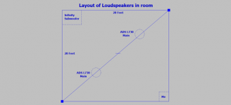
Layout of actors part#1.
I feel it is important for the DIYer to imagine my presence and the loudspeakers in my listening-hobby room. Where's everything sit and how's all this work?
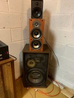
The layout of the room is attached. I sit 2 feet from the corner. The angled stereo loudspeakers beam energy at me. The enclosed Infinity DVC woofer sits at the opposite corner of the room diagonal.
I gladly sit in the direct path of standing waves [preferably attenuated] for subjective assessment. Torture or fun?
The picture of the woofer is attached. I had put the Infinity driver in this ancient loudspeaker box. The midrange and cone tweeters seal the box.
I have many loudspeaker pairs in this hobby room. To the left of the Infinity woofer is a Whaferdate 70W which my neighbor gave me when he moved to a senior retirement facilty. Sand-Heavy! A Polk 42 vented bookshelf sits above the woofer and its topped with an L300C ADS loudspeaker.
The twin set of these loudspeakers sits in the corner to the Right ADS L730 main speaker. This orthogonal corner has its independent share of standing waves.
They idle; but I 'll using one or more loudspeaker in my studies.
I 'll talk operation of system in a following part#2 post.
Best
Anton
I feel it is important for the DIYer to imagine my presence and the loudspeakers in my listening-hobby room. Where's everything sit and how's all this work?
The layout of the room is attached. I sit 2 feet from the corner. The angled stereo loudspeakers beam energy at me. The enclosed Infinity DVC woofer sits at the opposite corner of the room diagonal.
I gladly sit in the direct path of standing waves [preferably attenuated] for subjective assessment. Torture or fun?
The picture of the woofer is attached. I had put the Infinity driver in this ancient loudspeaker box. The midrange and cone tweeters seal the box.
I have many loudspeaker pairs in this hobby room. To the left of the Infinity woofer is a Whaferdate 70W which my neighbor gave me when he moved to a senior retirement facilty. Sand-Heavy! A Polk 42 vented bookshelf sits above the woofer and its topped with an L300C ADS loudspeaker.
The twin set of these loudspeakers sits in the corner to the Right ADS L730 main speaker. This orthogonal corner has its independent share of standing waves.
They idle; but I 'll using one or more loudspeaker in my studies.
I 'll talk operation of system in a following part#2 post.
Best
Anton
Attachments
Calculations
Hello nicotin78,
I could not easily find the following in your simulation which is extensive. I am recounting it for myself and all so as to takle the DVC woofer case.
The first 5 pages of the TI linked document in your post #113 did a a great job explaining the electret, and its operation. Notably the conversion of SPL in dB at the electret to the voltage output [Vout] of its transimpedance amplifier. The resultant important value is:
[Vout] = 1.228 Vrms = 100 dB [SPL] [Equation 1]
Another relevant conversion is 100 dB [SPL] = 2 Pascals = 0.02 millibar atmospheric pressure. [Equation 2]
1. [Vout] from the electret module is then sent to an inverting power amplifer which drives a woofer.
2. The performance of the woofer is normally specified [by example here] as: 100dB [SPL] at 1 meter due to injecting it with 1 W AC power.
3. The distance between the electret and the woofer is ~3 inches or 0.077 meters per the description the device described by Mr. Pass.
4. The woofer is asked to generate an inverted 100 dB [SPL] wave at the electret [0.077 meter away] to counteract the standing wave.
5. The woofer thus generates an atmospheric sucking pressure of 0.02 millibars to oblitarate the offending wave.
6. The bottom line is: There's an excursion or woofer-cone displacement associated with this 0.02 millibar vacuum it creates; which is enabled by a certain input Watt power to it.
Best wishes
Anton
Hello Anton,
FIY, I discovered yesterday that there is mistake in the electrical part of thé speaker model : thé gain of thé current controlled voltage source should bé -BL and not BL. Thé tension(voltage) indices vu thé mechanical circuit should counter act thé tension at thé terminals of thé voice coil(sorry for m'y english).
I did some mesurements over thé weekend, i'll Come back mater with thé résults.
Hello nicotin78,
I look forward to your results. Your English is fine.
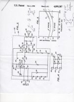
Mr. Pass shows the schematic of his patented device which was later named the Shadow. It is as actual as any similar schematic published with values of the components etc. I have not seen this specific one.
Please note that the voltage output of the condenser microphone [22]; which may well be an electret is buffered by the BJT [28]. This suggested the microphone's output does not need further amplification; possibly meaning the TI transimpedance module you have is not needed. Let's then play this number game in the absence of actual component values:
Suppose the microphone's buffered voltage output is 50 mV, and the voltage gain of the power amp [70] equal 30X. It follows that Vout at the loudspeaker [26] terminal [say 4 Ohms] is equal to [0.05 V X 30 = 1.5 V]. The amp's power output is this V squared divided by 4 = 0.6 W.
The above assessment may suggest a "boundary" for the expected in-process measurements.
Best wishes
Anton
I look forward to your results. Your English is fine.
Mr. Pass shows the schematic of his patented device which was later named the Shadow. It is as actual as any similar schematic published with values of the components etc. I have not seen this specific one.
Please note that the voltage output of the condenser microphone [22]; which may well be an electret is buffered by the BJT [28]. This suggested the microphone's output does not need further amplification; possibly meaning the TI transimpedance module you have is not needed. Let's then play this number game in the absence of actual component values:
Suppose the microphone's buffered voltage output is 50 mV, and the voltage gain of the power amp [70] equal 30X. It follows that Vout at the loudspeaker [26] terminal [say 4 Ohms] is equal to [0.05 V X 30 = 1.5 V]. The amp's power output is this V squared divided by 4 = 0.6 W.
The above assessment may suggest a "boundary" for the expected in-process measurements.
Best wishes
Anton
- Home
- Amplifiers
- Pass Labs
- DIY the device of US Patent 4,899,387